HSMS-2817-BLK 查看數據表(PDF) - HP => Agilent Technologies
零件编号
产品描述 (功能)
生产厂家
HSMS-2817-BLK Datasheet PDF : 10 Pages
| |||
5
Applications Information
Introduction —
Product Selection
Agilent’s family of Schottky
products provides unique solu-
tions to many design problems.
The first step in choosing the right
product is to select the diode type.
All of the products in the
HSMS-282x family use the same
diode chip, and the same is true of
the HSMS-281x and HSMS-280x
families. Each family has a
different set of characteristics
which can be compared most
easily by consulting the SPICE
parameters in Table 1.
A review of these data shows that
the HSMS-280x family has the
highest breakdown voltage, but at
the expense of a high value of
series resistance (Rs). In applica-
tions which do not require high
voltage the HSMS-282x family,
with a lower value of series
resistance, will offer higher
current carrying capacity and
better performance. The HSMS-
281x family is a hybrid Schottky
(as is the HSMS-280x), offering
lower 1/f or flicker noise than the
HSMS-282x family.
In general, the HSMS-282x family
should be the designer’s first
choice, with the -280x family
reserved for high voltage applica-
tions and the HSMS-281x family
for low flicker noise applications.
Assembly Instructions
SOT-323 PCB Footprint
A recommended PCB pad layout
for the miniature SOT-323 (SC-70)
package is shown in Figure 6
(dimensions are in inches). This
layout provides ample allowance
for package placement by auto-
mated assembly equipment
without adding parasitics that
could impair the performance.
Table 1. Typical SPICE Parameters.
Parameter Units HSMS-280x
BV
V
CJ0
pF
EG
eV
IBV
A
IS
A
N
RS
Ω
PB (VJ)
V
PT (XTI)
M
75
1.6
0.69
1 E-5
3 E-8
1.08
30
0.65
2
0.5
HSMS-281x
25
1.1
0.69
1 E-5
4.8 E-9
1.08
10
0.65
2
0.5
HSMS-282x
15
0.7
0.69
1 E-4
2.2 E-8
1.08
6.0
0.65
2
0.5
0.026
0.07
0.035
0.016
Figure 6. PCB Pad Layout
(dimensions in inches).
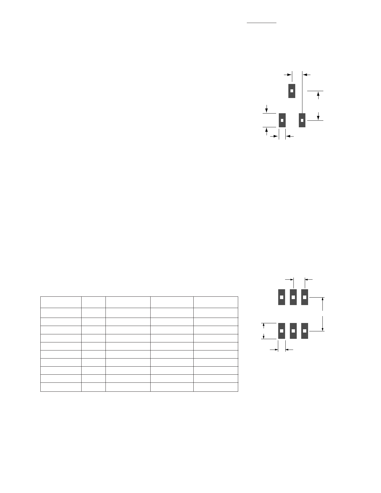
Assembly Instructions
SOT-363 PCB Footprint
A recommended PCB pad layout
for the miniature SOT-363 (SC-70,
6 lead) package is shown in
Figure 7 (dimensions are in
inches). This layout provides
ample allowance for package
placement by automated assembly
equipment without adding
parasitics that could impair the
performance.
0.026
0.035
0.075
0.016
Figure 7. PCB Pad Layout
(dimensions in inches).
Share Link: 