ISL62881 查看數據表(PDF) - Renesas Electronics
零件编号
产品描述 (功能)
生产厂家
ISL62881 Datasheet PDF : 35 Pages
| |||
ISL62881, ISL62881B
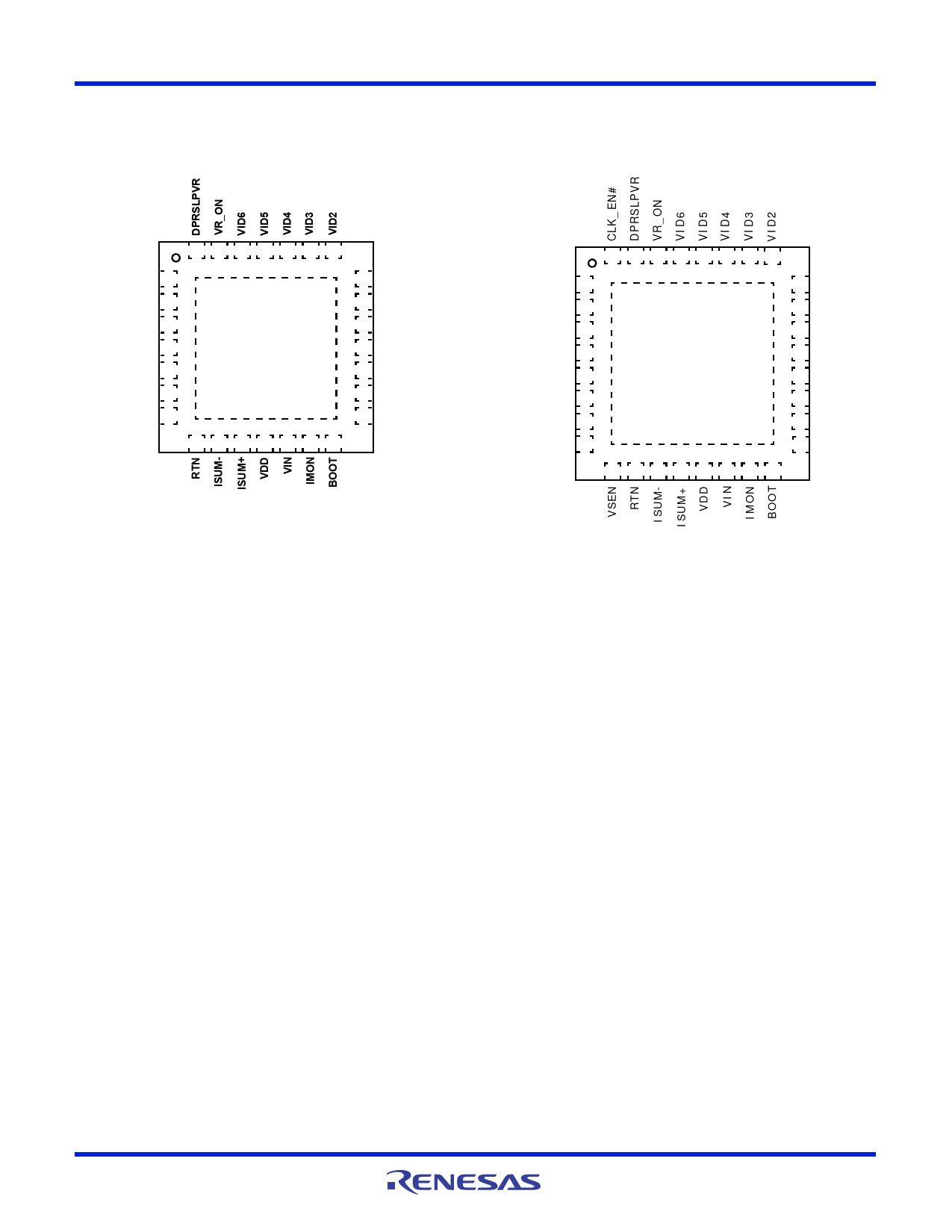
Pin Configurations
ISL62881
(28 LD TQFN)
TOP VIEW
ISL62881B
(32 LD TQFN)
TOP VIEW
28 27 26 25 24 23 22
CLK_EN# 1
PGOOD 2
RBIAS 3
VW 4
COMP 5
FB 6
VSEN 7
GND PAD
(BOTTOM)
21 VID1
20 VID0
19 VCCP
18 LGATE
17 VSSP
16 PHASE
15 UGATE
8 9 10 11 12 13 14
32 31 30 29 28 27 26 25
PGOOD 1
RBIAS 2
VR_TT# 3
NTC 4
GND 5
VW 6
COMP 7
FB 8
GND PAD
(BOTTOM)
24 VID1
23 VID0
22 VCCP
21 LGATEb
20 LGATEa
19 VSSP
18 PHASE
17 UGATE
9 10 11 12 13 14 15 16
Pin Function Descriptions
GND (Bottom Pad)
Signal common of the IC. Unless otherwise stated, signals are
referenced to the GND pin.
CLK_EN#
Open drain output to enable system PLL clock; goes active 13
switching cycles after Vcore is within 10% of Vboot.
PGOOD
Power-Good open-drain output indicating when the regulator is
able to supply regulated voltage. Pull-up externally with a 680
resistor to VCCP or 1.9k to 3.3V.
RBIAS
A resistor to GND sets internal current reference. A 147k
resistor sets the controller for CPU core application and a 47k
resistor sets the controller for GPU core application.
VR_TT#
Thermal overload output indicator.
NTC
Thermistor input to VR_TT# circuit.
VW
A resistor from this pin to COMP programs the switching
frequency (8k gives approximately 300kHz).
FN6924 Rev 3.00
June 16, 2011
COMP
This pin is the output of the error amplifier. Also, a resistor across this
pin and GND adjusts the overcurrent threshold.
FB
This pin is the inverting input of the error amplifier.
VSEN
Remote core voltage sense input. Connect to microprocessor die.
RTN
Remote voltage sensing return. Connect to ground at
microprocessor die.
ISUM- and ISUM+
Droop current sense input.
VDD
5V bias power.
VIN
Battery supply voltage, used for feed-forward.
IMON
An analog output. IMON outputs a current proportional to the
regulator output current.
BOOT
Connect an MLCC capacitor across the BOOT and the PHASE
pins. The boot capacitor is charged through an internal boot
Page 2 of 35
Share Link: 