LT1316 查看數據表(PDF) - Linear Technology
零件编号
产品描述 (功能)
生产厂家
LT1316 Datasheet PDF : 16 Pages
| |||
LT1316
APPLICATIONS INFORMATION
then adding in the amount of overshoot that will occur due
to turn-off delay of the power transistor. This turn-off
delay is approximately 300ns.
Peak switch current = DC current limit from graph +
VIN/L(turn-off delay)
Example:
Set peak switch current to 100mA for: VIN = 2V,
L = 33µH
Overshoot = VIN/L(turn-off delay) = (2/33µH)(300ns)
= 18.2mA
Refer to RSET graph and locate
(100mA – 18.2mA) ≈ 82mA
RSET ≈ 33k
Calculating Duty Cycle
For a boost converter running in continuous conduction
mode, duty cycle is constrained by VIN and VOUT according
to the equation:
DC
=
VOUT – VIN + VD
VOUT – VSAT + VD
where VD = diode voltage drop ≈ 0.4V and VSAT = switch
saturation voltage ≈ 0.2V.
If the duty cycle exceeds the LT1316’s minimum specified
duty cycle of 0.73, the converter cannot operate in con-
tinuous conduction mode and must be designed for
discontinuous mode operation.
Inductor Selection and Peak Current Limit for
Continuous Conduction Mode
Peak current and inductance determine available output
power. Both must be chosen properly. If peak current or
inductance is increased, output power increases. Once
output power or current and duty cycle are known, peak
current can be set by the following equation, assuming
continuous mode operation:
IPEAK
=
2(IOUT)
1 – DC
(1)
Inductance can now be calculated using the peak current:
L=
VOUT – VIN +
0.4(IPEAK)
VD
(tOFF)
(2)
where tOFF = 2µs and VD = 0.4V.
As a result of equations 1 and 2, ripple current during
switching will be 40% of the peak current (see Figure 2).
Using these equations at the specified IOUT, the part is
delivering approximately 60% of its maximum output
power. In other words, the part is operating on a 40%
reserve. This is a safe margin to use and can be decreased
if input voltage and output current are tightly controlled.
For some applications, this recommended inductor size
may be too large. Inductance can be reduced but available
output power will decrease. Also, ripple current during
switching will increase and may cause discontinuous
operation. Discontinuous operation occurs when
inductor current ramps down to zero at the end of each
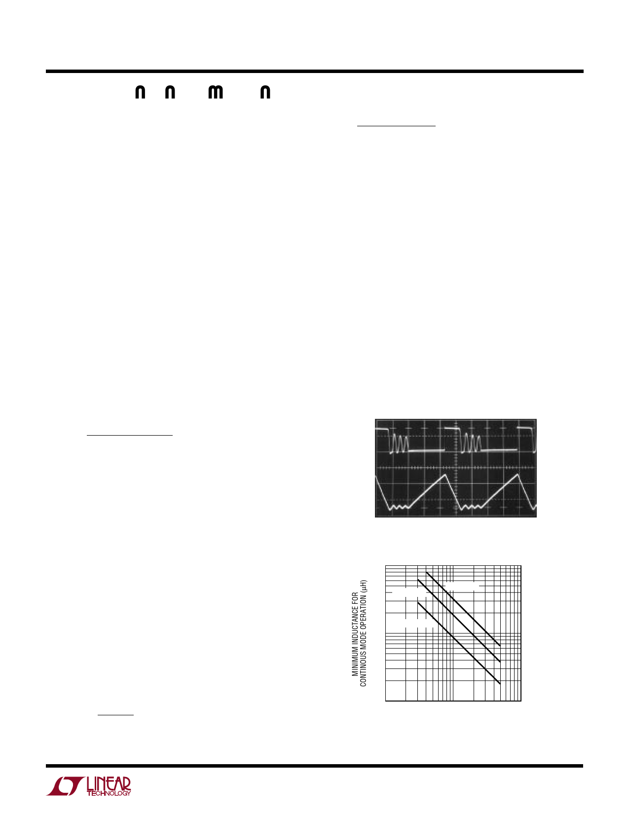
switch cycle (see Figure 4). Shown in Figure 5 is minimum
inductance vs peak current for the part to remain in
continuous mode.
0mA
INDUCTOR
CURRENT
100mA/DIV
SW PIN
5V/DIV
2µs/DIV
1316 F04
Figure 4. Discontinuous Mode Operation
1000
5V TO 12V
5V TO 18V
2V TO 5V
100
10
10
100
1000
PEAK CURRENT (mA)
1316 F05
Figure 5. Minimum Inductance vs Peak Current
for Continuous Mode Operation
7
Share Link: 