LT1120CH 查看數據表(PDF) - Linear Technology
零件编号
产品描述 (功能)
生产厂家
LT1120CH Datasheet PDF : 12 Pages
| |||
LT1120
APPLICATIO S I FOR ATIO
Reference
Internal to the LT1120 is a 2.5V trimmed class B output
reference. The reference was designed to be able to source
or sink current so it could be used in supply splitting
applications as well as a general purpose reference for
external circuitry. The design of the reference allows it to
source typically 4mA or 5mA and sink 2mA. The available
source and sink current decreases as temperature in-
creases. It is sometimes desirable to decrease the AC
output impedance by placing an output capacitor on them.
The reference in the LT1120 becomes unstable with large
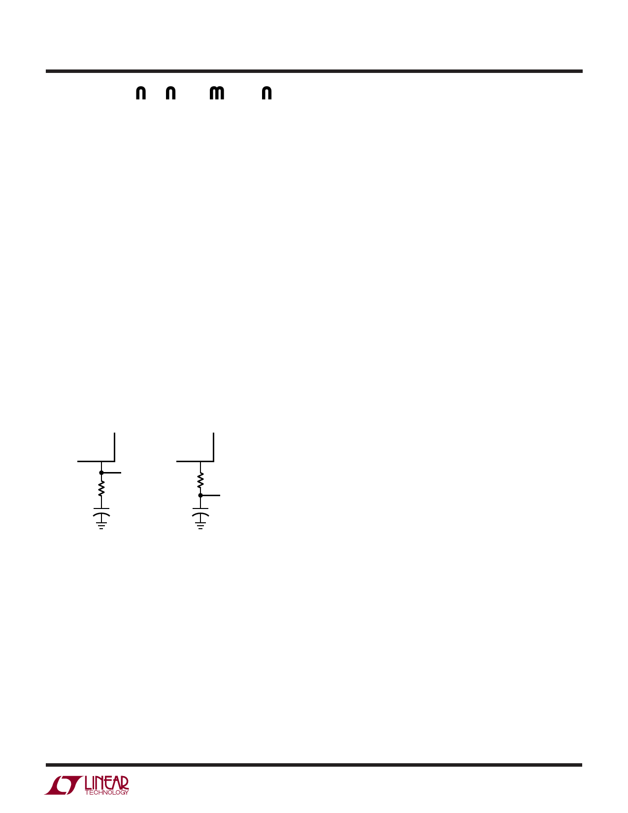
capacitive loads placed directly on it. When using an
output capacitor, about 20Ω should be used to isolate the
capacitor from the reference pin. This 20Ω resistor can be
placed directly in series with the capacitor or alternatively
the reference line can have 20Ω placed in series with it and
then a capacitor to ground. This is shown in Figure 1. Other
than placing large capacitive loads on the reference, no
other precautions are necessary and the reference is
stable with nominal stray capacitances.
REF
6
OUTPUT
20Ω
OR
+
10μF
REF
6
20Ω
OUTPUT
+
10μF
1120 F01
Figure 1. Bypassing Reference
Overload Protection
The main regulator in the LT1120 is current limited at
approximately 250mA. The current limit is stable with both
input voltage and temperature.
Like most other IC regulators, a minimum load is required
on the output of the LT1120 to maintain regulation. For
most standard regulators this is normally specified at
5mA. Of course, for a micropower regulator this would be
a tremendously large current. The output must be large
enough to absorb all the leakage current of the pass
transistor at the maximum operating temperature. It also
effects the transient response; low output currents have
long recovery times from load transients. At high operat-
ing temperatures the minimum load current increases and
having too low of a load current may cause the output to
go unregulated. Devices are tested for minimum load
current at high temperature. The output voltage setting
resistors to the feedback terminal can usually be used to
provide the minimum load current.
Frequency Compensation
The LT1120 is frequency compensated by a dominant pole
on the output. An output capacitor of 10μF is usually large
enough to provide good stability. Increasing the output
capacitor above 10μF further improves stability. In order
to ensure stability, a feedback capacitor is needed between
the output pin and the feedback pin. This is because stray
capacitance can form another pole with the large value of
feedback resistors used with the LT1120. Also, a feedback
capacitor minimizes noise pickup and improves ripple
rejection.
With the large dynamic operating range of the output
current, 10000:1, frequency response changes widely.
Low AC impedance capacitors are needed to insure stabil-
ity. While solid tantalum are best, aluminum electrolytics
can be used but larger capacitor values may be needed.
1120fd
7
Share Link: 