LT1684 查看數據表(PDF) - Linear Technology
零件编号
产品描述 (功能)
生产厂家
LT1684 Datasheet PDF : 16 Pages
| |||
LT1684
APPLICATIO S I FOR ATIO
For applications that are extremely output ripple sensitive,
additional carrier rejection can be accomplished by modi-
fying the output filter/amplifier characteristics such as
implementing elliptical filter characteristics with a lower
cutoff frequency or implementation of additional poles.
Filter Design and Component Selection
The ring tone information represented in the low fre-
quency component of the input PWM signal is retrieved
using an active filter. This filter also generates the appro-
priate low frequency gain required to produce the high
voltage output signal and references the output to ground
(or other system reference). The frequency and gain
characteristics of this circuit element are both configurable
by the appropriate choice of external passive filter ele-
ments. Because of the active tracking supply mode of
operation, conventional active filter topologies cannot be
used. Most amplifier/filter topologies can, however, be
“transformed” into active tracking supply topologies.
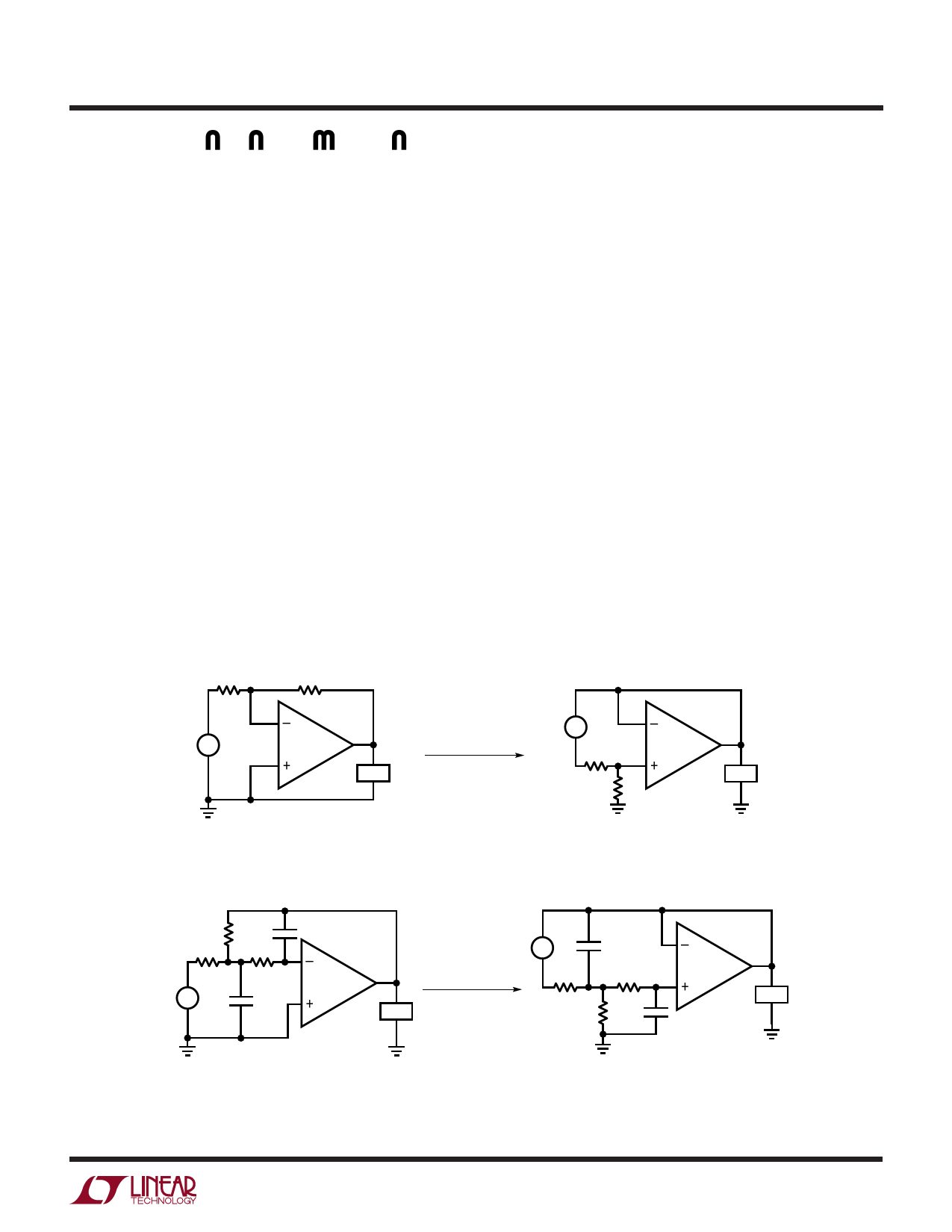
A conventional amplifier circuit topology can be “trans-
formed” into an active tracking supply amplifier circuit by:
a) Inverting the amplifier signal polarity (swap amplifier +
and – connections) and input source polarity.
b) Referencing all signals to the output except the feed-
back elements, which are referenced to ground (swap
output and ground).
A variety of amplifier/filter configurations can be realized
using the transformation technique. A 2-pole filter is
generally adequate for most ringer applications. Due to the
relative simplicity of infinite-gain Multiple Feedback (MFB)
configurations, these filters are good candidates for ringer
applications. Component selection and active tracking
supply transformation will be described for the following
2-pole MFB infinite-gain lowpass filter.
Conventional Amplifier Configuration
R1
R2
–
+
VIN
–
+
LOAD
TRANSFORMATION
Active Tracking Supply Amplifier
+
VIN
–
R1
–
+
R2
LOAD
Lowpass Mulitple Feedback Active Filter
Active Tracking Supply Lowpass
Multiple Feedback Filter
R2 C2
R1
R3
–
+
VIN
C1
+
–
+
–
VIN
C1
–
TRANSFORMATION
R1
R3
+
LOAD
R2
C2
LOAD
1684 F01
9
Share Link: 