MC12429FN 查看數據表(PDF) - Motorola => Freescale
零件编号
产品描述 (功能)
生产厂家
MC12429FN Datasheet PDF : 10 Pages
| |||
MC12429
be applications in which overall performance is being
degraded due to system power supply noise. The power
supply filter and bypass schemes discussed in this section
should be adequate to eliminate power supply noise related
problems in most designs.
Jitter Performance of the MC12429
The MC12429 exhibits long term and cycle–to–cycle jitter
which rivals that of SAW based oscillators. This jitter
performance comes with the added flexibility one gets with a
synthesizer over a fixed frequency oscillator.
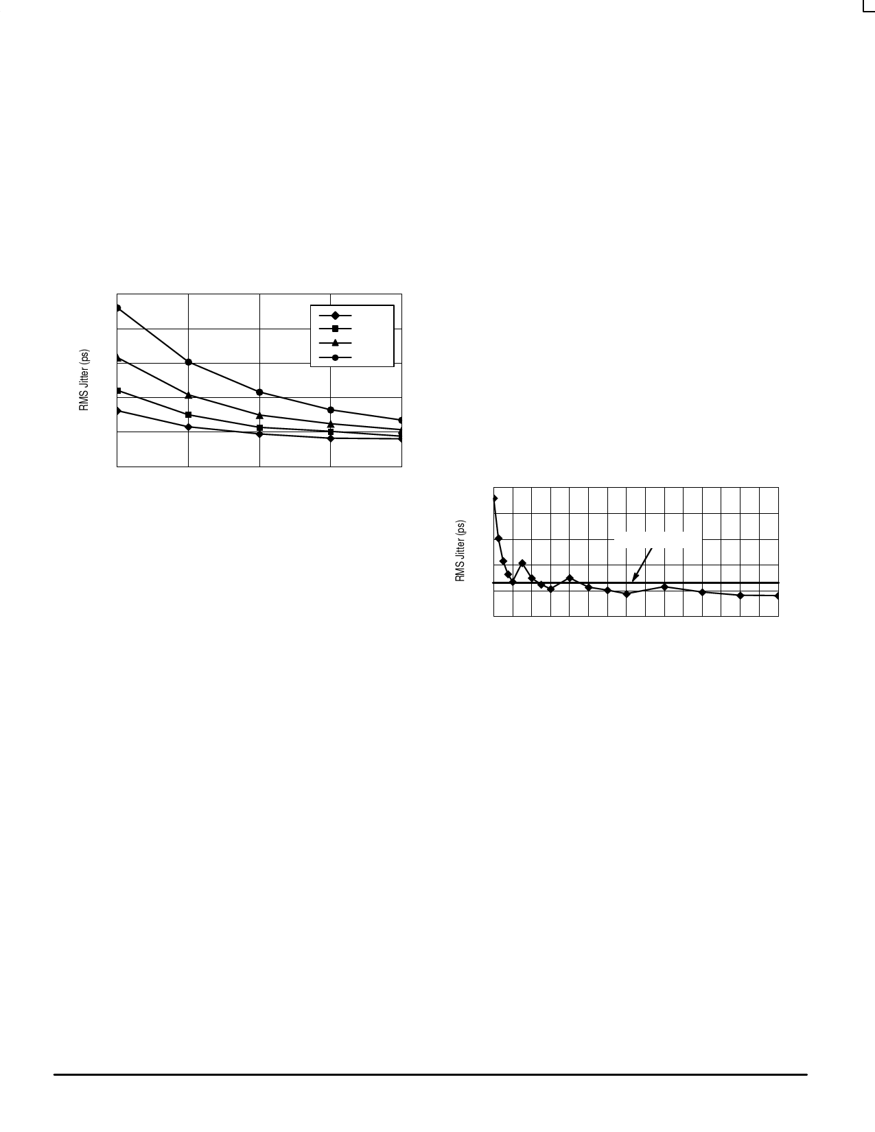
25
N=2
20
N=4
N=8
15
N=16
10
5
0
400
500
600
700
800
VCO Frequency (MHz)
Figure 7. RMS PLL Jitter versus VCO Frequency
Figure 7 illustrates the RMS jitter performance of the
MC12429 across its specified VCO frequency range. Note
that the jitter is a function of both the output frequency as well
as the VCO frequency, however the VCO frequency shows a
much stronger dependence. The data presented has not
been compensated for trigger jitter, this fact provides a
measure of guardband to the reported data. In addition the
data represents long term period jitter, the cycle–to–cycle
jitter could not be measured to the level of accuracy required
with available test equipment but certainly will be smaller
than the long term period jitter.
The most commonly specified jitter parameter is
cycle–to–cycle jitter. Unfortunately with today’s high
performance measurement equipment there is no way to
measure this parameter for jitter performance in the class
demonstrated by the MC12429. As a result different methods
are used which approximate cycle–to–cycle jitter. The typical
method of measuring the jitter is to accumulate a large
number of cycles, create a histogram of the edge placements
and record peak–to–peak as well as standard deviations of
the jitter. Care must be taken that the measured edge is the
edge immediately following the trigger edge. The
oscilloscope cannot collect adjacent pulses, rather it collects
pulses from a very large sample of pulses. It is safe to
assume that collecting pulse information in this mode will
produce period jitter values somewhat larger than if
consecutive cycles (cycle–to–cycle jitter) were measured. All
of the jitter data reported on the MC12429 was collected in
this manner.
Figure 8 shows the jitter as a function of the output
frequency. For the 12429 this information is probably of more
importance. The flat line represents an RMS jitter value that
corresponds to an 8 sigma ±25ps peak–to–peak long term
period jitter. The graph shows that for output frequencies
from 87.5 to 400MHz the jitter falls within the ±25ps
peak–to–peak specification. The general trend is that as the
output frequency is decreased the output edge jitter will
increase.
25
20
15
6.25ps Reference
10
5
0
25 50 75 100 125 150 175 200 225 250 275 300 325 350 375 400
Output Frequency (MHz)
Figure 8. RMS Jitter versus Output Frequency
The jitter data presented should provide users with
enough information to determine the effect on their overall
timing budget. The jitter performance meets the needs of
most system designs while adding the flexibility of frequency
margining and field upgrades. These features are not
available with a fixed frequency SAW oscillator.
MOTOROLA
8
TIMING SOLUTIONS
BR1333 — Rev 6
Share Link: 