BF821 查看數據表(PDF) - General Semiconductor
零件编号
产品描述 (功能)
生产厂家
BF821 Datasheet PDF : 2 Pages
| |||
BF821, BF823
ELECTRICAL CHARACTERISTICS
Ratings at 25 °C ambient temperature unless otherwise specified
Symbol
Min.
Typ.
Collector-Base Breakdown Voltage BF821 –V(BR)CBO 300
–
at –IC = 100 µA, IE = 0
BF823 –V(BR)CBO 250
–
Collector-Emitter Breakdown Voltage BF823 –V(BR)CEO 250
–
at –IC = 10 mA, IB = 0
Collector-Emitter Breakdown Voltage BF821 –V(BR)CER 300
–
at RBE = 2.7 kΩ, –IC = 10 mA
Emitter-Base Breakdown Voltage
at –IE = 100 µA, IC = 0
–V(BR)EBO 5
–
Collector-Base Cutoff Current
at –VCB = 200 V, IE = 0
–ICBO
–
–
Collector-Emitter Cutoff Current
at RBE = 2.7 kΩ, –VCE = 250 V
at RBE = 2.7 kΩ, –VCE = 200 V, Tj = 150 °C
–ICER
–ICER
Collector Saturation Voltage
at –IC = 30 mA, –IB = 5 mA
–VCEsat
–
–
DC Current Gain
at –VCE = 20 V, –IC = 25 mA
hFE
50
–
Gain-Bandwidth Product
at –VCE = 10 V, –IC = 10 mA
fT
60
–
Feedback Capacitance
at –VCE = 30 V, –IC = 0, f = 1 MHz
Cre
–
–
Thermal Resistance Junction to Ambient Air
RthJA
–
–
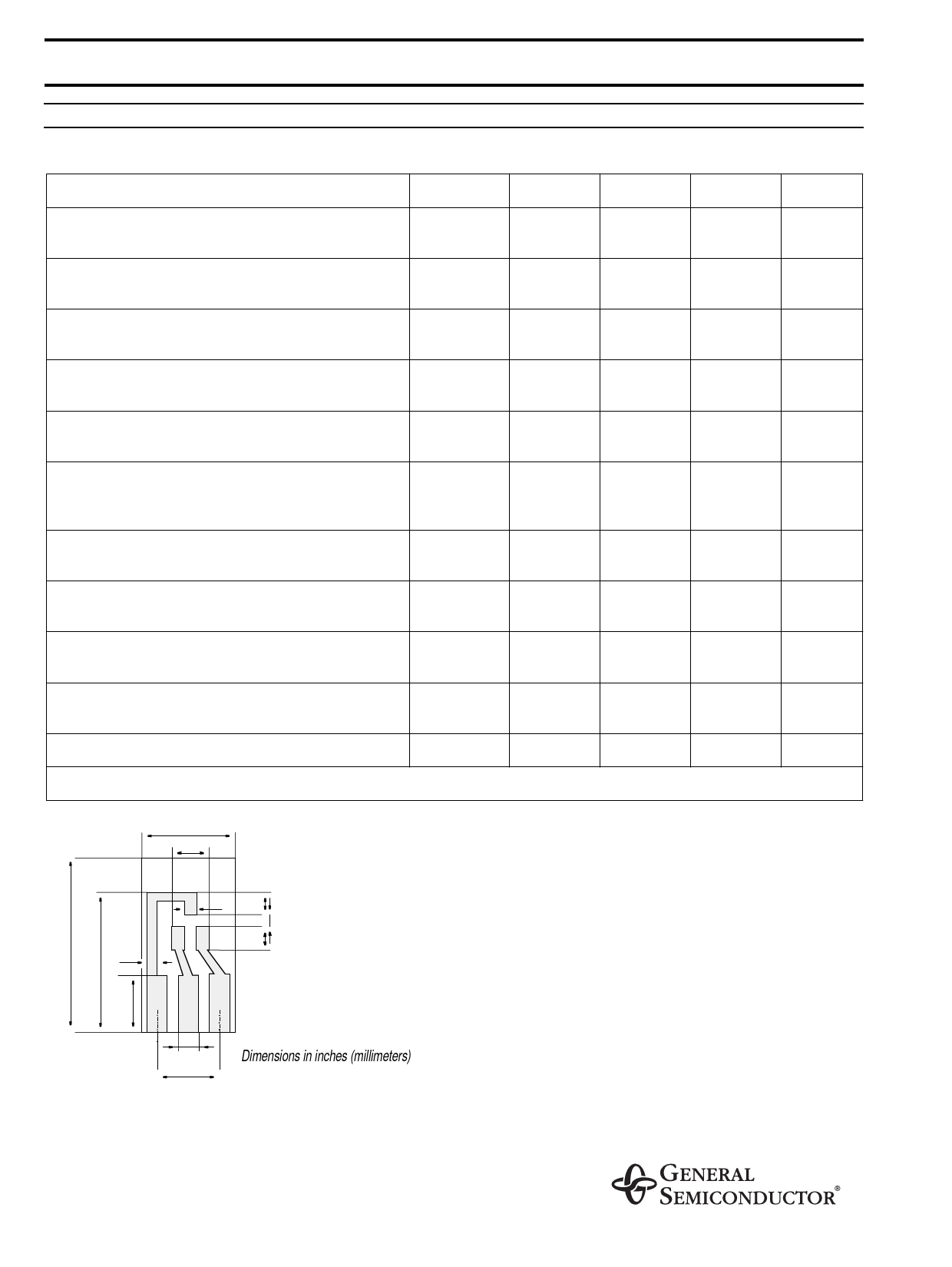
1) Device on fiberglass substrate, see layout
.30 (7.5)
.12 (3)
.59 (15)
.03 (0.8)
.47 (12)
0.2 (5)
.04 (1) .08 (2)
.04 (1)
.08 (2)
.06 (1.5)
.20 (5.1)
Dimensions in inches (millimeters)
Layout for RthJA test
Thickness: Fiberglass 0.059 in (1.5 mm)
Copper leads 0.012 in (0.3 mm)
Max.
Unit
–
V
–
V
–
V
–
V
–
V
10
nA
50
10
0.8
–
–
1.6
4301)
nA
µA
V
–
MHz
pF
K/W
Share Link: 