CR5627 查看數據表(PDF) - Philips Electronics
零件编号
产品描述 (功能)
生产厂家
CR5627 Datasheet PDF : 8 Pages
| |||
Philips Semiconductors
Triple video driver hybrid amplifier
Product specification
CR5627
handbook, full pagewidth
input
50 Ω
VS
C3
C1
C2
R1
R2
R3
C4
1
2
4
CR5627
3
output
CL
PULSE
GENERATOR
TEST
FIXTURE
CR5627
POWER
SUPPLY
FET
PROBE
SAMPLING
OSCILLOSCOPE
MBG371
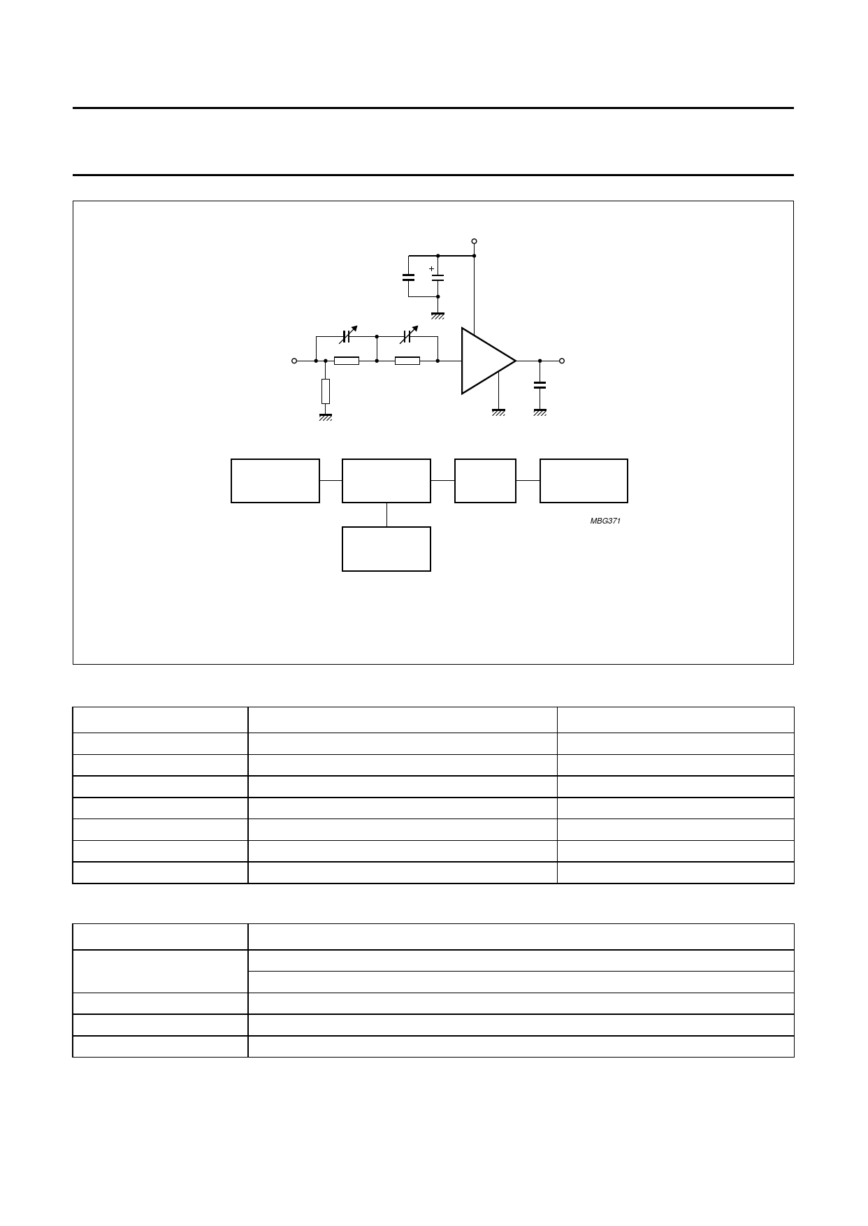
Test-circuit for one of the three CRT amplifiers.
Fig.6 CRT amplifier test-circuit and block diagram.
Components used in test-circuit (see Fig.6)
DESIGNATION
C1
C2
C3
C4
R1
R2
R3
DESCRIPTION
variable capacitor
variable capacitor
chip capacitor
electrolytic capacitor
resistor
resistor
resistor
VALUE
10 to 160 pF (typ. 90 pF)
10 to 160 pF (typ. 100 pF)
10 nF
4.7 µF; 160 V
typ. 348 Ω
typ. 82 Ω
50 Ω
Equipment used in test-circuit (see Fig.6)
EQUIPMENT
Pulse generator
Power supply
FET probe
Sampling oscilloscope
TYPE DESCRIPTION
Le Croy; Model 9210 with unit 9212
Philips; Model PM5785B (125 MHz) with internal DC offset
Philips; Model PE1541, 80 V
Philips; Model PM8943, attenuation 100 : 1
Tektronix; Model 11803, sampling head SD24
1995 Oct 09
5
Share Link: 