CS8900-CQ 查看數據表(PDF) - Cirrus Logic
零件编号
产品描述 (功能)
生产厂家
CS8900-CQ Datasheet PDF : 132 Pages
| |||
CS8900
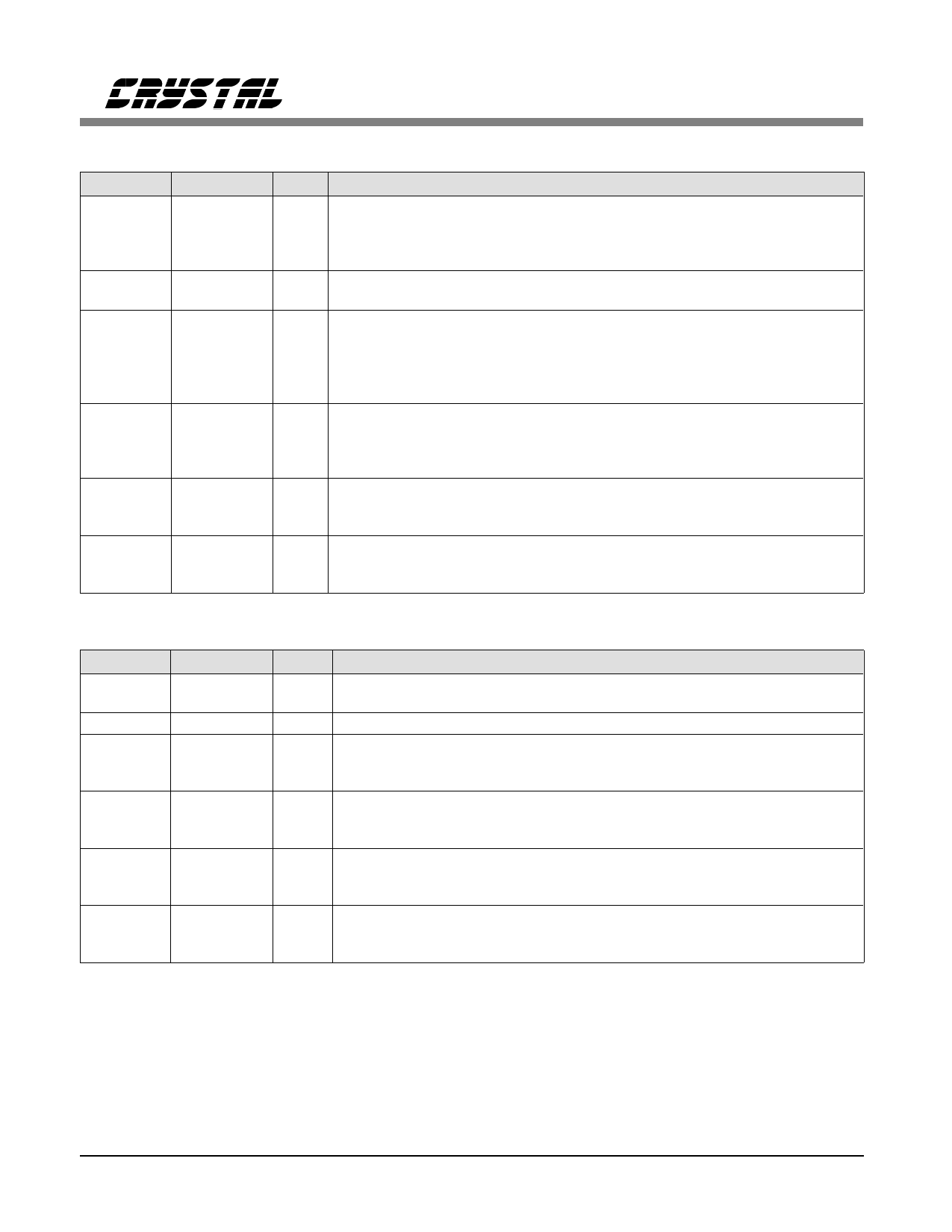
ISA Bus Interface (continued)
Symbol
IOCHRDY
SBHE
INTRQ0
INTRQ1
INTRQ2
INTRQ3
DMARQ0
DMARQ1
DMARQ2
DMACK0
DMACK1
DMACK2
CHIPSEL
Pin Number Type
Description
64
OD24 I/O Channel Ready: When driven low, this open-drain, active-high output
extends I/O Read and Memory Read cycles to the CS8900. This output is
functional when the IOCHRDYE bit in the Bus Control register (Register
17) is clear. This pin is always tri-stated when the IOCHRDYE bit is set.
36
I System Bus High Enable: Active-low input indicates a data transfer on
the high byte of the System Data Bus (SD8-SD15).
32
O24ts Interrupt Request: Active-high output indicates the presence of an
31
interrupt event. Interrupt Request goes low once the Interrupt Status
30
Queue (ISQ) is read as all 0’s. Only one Interrupt Request output is used
35
(one is selected during configuration). All non-selected Interrupt Request
outputs are placed in a high-impedance state. (See sections 3.2 and 5.1.)
15
O24ts DMA Request: Active-high, tri-stateable output used by the CS8900 to
13
request a DMA transfer. Only one DMA Request output is used (one is
11
selected during configuration). All non-selected DMA Request outputs are
placed in a high-impedance state.
16
I DMA Acknowledge: Active-low input indicates acknowledgment by the
14
host of the corresponding DMA Request output.
12
7
I Chip Select: Active-low input generated by external Latchable Address
bus decode logic when a valid memory address is present on the ISA bus.
If Memory Mode operation is not needed, CHIPSEL should be tied low.
EEPROM and Boot PROM Interface
Symbol Pin Number
EESK
4
EECS
3
EEDataIn
6
ELCS
2
EEDataOut
5
CSOUT
17
Type
O4
O4
Iw
B4w
O4
O4
Description
EEPROM Serial Clock: Serial clock used to clock data into or out of the
EEPROM.
EEPROM Chip Select: Active-high output used to select the EEPROM.
EEPROM Data In: Serial input used to receive data from the EEPROM.
Connects to the DO pin on the EEPROM. EEDataIn is also used to sense
the presence of the EEPROM.
External Logic Chip Select: Bi-directional signal used to configure
external Latchable Address (LA) decode logic. If external LA decode logic
is not needed, ELCS should be tied low.
EEPROM Data Out: Serial output used to send data to the EEPROM.
Connects to the DI pin on the EEPROM. When TESTSEL is low, this pin
becomes the output for the Boundary Scan Test.
Chip Select for External Boot PROM: Active-low output used to select
an external Boot PROM when the CS8900 decodes a valid Boot PROM
memory address.
Pin Types:
dI = Differential Input Pair
I
dO = Differential Output Pair
O
B = Bi-Directional with Tri-State Output P
OD = Open Drain Output
= Input
= Output
= Power
G = Ground
ts = Tri-State
w = Internal Weak Pullup
Digital outputs are followed by drive in mA (Example: OD24 = Open Drain Output with 24 mA drive).
10
DS150PP2
Share Link: 