MAX791M(1995) 查看數據表(PDF) - Maxim Integrated
零件编号
产品描述 (功能)
生产厂家
MAX791M Datasheet PDF : 20 Pages
| |||
Microprocessor Supervisory Circuit
ABSOLUTE MAXIMUM RATINGS
Input Voltage (with respect to GND)
VCC .......................................................................-0.3V to +6V
VBATT..................................................................-0.3V to + 6V
All Other Inputs.....................................-0.3V to (VOUT + 0.3V)
Input Current
VCC Peak ..........................................................................1.0A
VCC Continuous ............................................................250mA
VBATT Peak ..................................................................250mA
VBATT Continuous ..........................................................25mA
GND, BATT ON .............................................................100mA
All Other Outputs ............................................................25mA
Continuous Power Dissipation (TA = +70°C)
Plastic DIP (derate 10.53mW/°C above +70°C) ..........842mW
Narrow SO (derate 8.70mW/°C above +70°C) ............696mW
CERDIP (derate 10.00mW/°C above +70°C) ...............800mW
Operating Temperature Ranges
MAX791C_ _ ......................................................O°C to +70°C
MAX791E_ _ ....................................................-40°C to +85°C
MAX791MJE ..................................................-55°C to +125°C
Storage Temperature Range .............................-65°C to +160°C
Lead Temperature (soldering, 10sec) .............................+300°C
Stresses beyond those listed under “Absolute Maximum Ratings” may cause permanent damage to the device. These are stress ratings only, and functional
operation of the device at these or any other conditions beyond those indicated in the operational sections of the specifications is not implied. Exposure to
absolute maximum rating conditions for extended periods may affect device reliability.
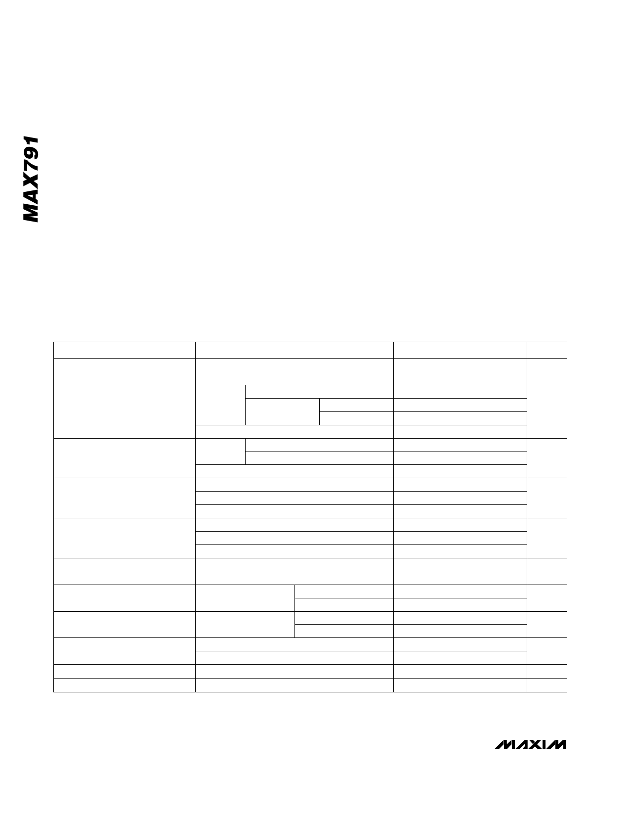
ELECTRICAL CHARACTERISTICS
(VCC = 4.75V to 5.5V, VBATT = 2.8V, TA = TMIN to TMAX, unless otherwise noted.)
PARAMETER
CONDITIONS
Operating Voltage Range
VCC, VBATT (Note 1)
VOUT in Normal
Operating Mode
VCC-to-VOUT On-Resistance
VOUT in Battery-Backup Mode
VBATT-to-VOUT On-Resistance
Supply Current in Normal
Operating Mode (Excludes IOUT)
Supply Current in Battery-Backup
Mode (Excludes IOUT) (Note 2)
VBATT Standby Current
(Note 3)
Battery-Switchover Threshold
Battery-Switchover Hysteresis
Low-Battery Detector Threshold
IOUT = 25mA
VCC = 4.5V IOUT = 250mA
MAX791C/E
MAX791M
VCC = 3V, VBATT = 2.8V, IOUT = 100mA
MAX791C/E
VCC = 4.5V MAX791M
VCC = 3V
VBATT = 4.5V, IOUT = 20mA
VBATT = 2.8V, IOUT = 10mA
VBATT = 2.0V, IOUT = 5mA
VBATT = 4.5V
VBATT = 2.8V
VBATT = 2.0V
VCC > VBATT - 1V
VCC < VBATT - 1.2V,
VBATT = 2.8V
VBATT + 0.2V ≤ VCC
Power up
Power down
TA = +25°C
TA = TMIN to TMAX
TA = +25°C
TA = TMIN to TMAX
MIN
TYP MAX
0
5.5
VCC - 0.05 VCC - 0.02
VCC - 0.3 VCC - 0.2
VCC - 0.40
VCC - 0.2 VCC - 0.12
0.8
1.2
0.8
1.6
1.2
2.0
VBATT - 0.3
VBATT - 0.25
VBATT - 0.15
8
15
13
25
17
30
50
150
0.04
1
5
-0.1
0.02
-1.0
0.02
VBATT + 0.03
VBATT - 0.03
60
2
UNITS
V
V
Ω
V
Ω
µA
µA
µA
V
mV
V
2 _______________________________________________________________________________________
Share Link: 