MAX791M(1995) 查看數據表(PDF) - Maxim Integrated
零件编号
产品描述 (功能)
生产厂家
MAX791M Datasheet PDF : 20 Pages
| |||
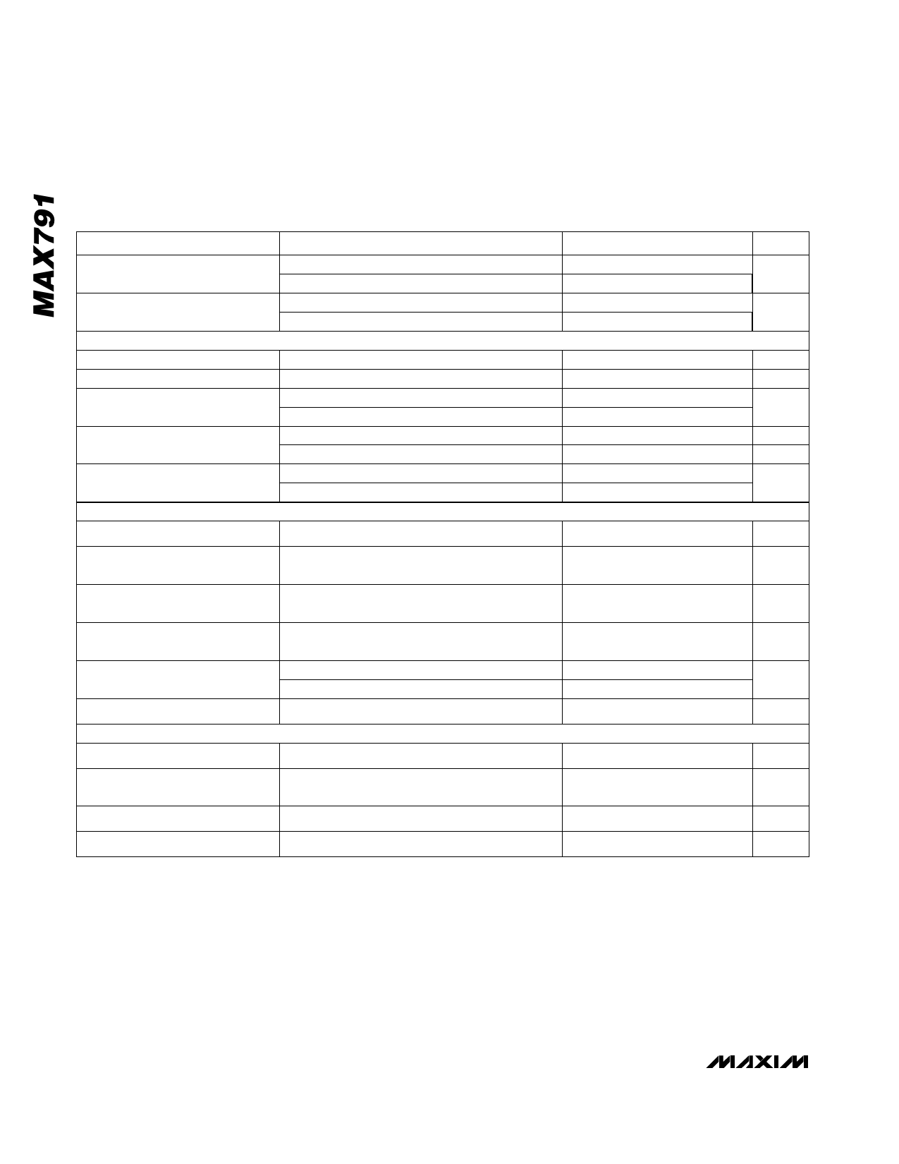
Microprocessor Supervisory Circuit
ELECTRICAL CHARACTERISTICS (continued)
(VCC = 4.75V to 5.5V, VBATT = 2.8V, TA = TMIN to TMAX, unless otherwise noted.)
PARAMETER
WDI Threshold Voltage
(Note 4)
WDI Input Current
POWER-FAIL COMPARATOR
PFI Input Threshold
PFI Leakage Current
–——–
PFO Output Voltage
–——–
PFO Short-Circuit Current
–——–
PFI-to-PFO Delay
CHIP-ENABLE GATING
–C—E– IN Leakage Current
–C—E– IN-to-C–—E– OUT Resistance
(Note 5)
–C—E– OUT Short-Circuit Current
(Reset Active)
–C—E– IN-to-C—E– OUT Propagation
Delay (Note 6)
–C—E– OUT Output Voltage High
(Reset Active)
–R—E—S—E—T–-to-–C—E– OUT Delay
MANUAL RESET INPUT
–M—R– Minimum Pulse Width
–M—R–-to
–————–
-RESET
Propagation Delay
–M—R– Threshold
–M—R– Pull-Up Current
VIH
VIL
WDI = 0V
WDI = VOUT
CONDITIONS
VCC = 5V
ISINK = 3.2mA
ISOURCE = 1µA, VCC = 5V
Output sink current
Output source current
VIN = -20mV, VOD = 15mV
VIN = 20mV, VOD = 15mV
Disabled mode
Enabled mode
Disabled mode, –C—E– OUT = 0V
50Ω source impedance driver, CLOAD = 50pF
VCC = 5V, IOUT = -100µA
VCC = 0V, VBATT = 2.8V, IOUT = 1µA
Power down
VCC = 5V
–M—R– = 0V
MIN
0.75 x VCC
TYP
-50
-10
20
MAX
0.8
50
UNITS
V
µA
1.20
1.25 1.30
V
±0.01 ±25
nA
0.4
V
3.5
60
mA
1
15
100
µA
15
µs
55
±0.005 ±1
µA
75
150
Ω
0.1
0.75
2.0
mA
6
10
ns
3.5
V
2.7
15
µs
25
15
µs
7
µs
1.25
V
23
250
µA
Note 1: Either VCC or VBATT can go to 0V, if the other is greater than 2.0V.
Note 2: The supply current drawn by the MAX791 from the battery (excluding IOUT) typically goes to 10µA when
(VBATT - 1V) < VCC < VBATT. In most applications, this is a brief period as VCC falls through this region.
Note 3: "+" = battery-discharging current, "-" = battery-charging current.
Note 4: WDI is internally connected to a voltage divider between VOUT and GND. If unconnected, WDI is driven to 1.6V (typ),
disabling the watchdog function.
Note 5:
Note 6:
The
The
chip-enable
chip-enable
resistance is
propagation
tested with VCC =
delay is measured
4.75V V –C—E– IN
from the 50%
=poVinC—t E–atO–CU—E–T
= VCC / 2.
IN to the 50%
point
at
C–—E–
OUT.
4 _______________________________________________________________________________________
Share Link: 