MAX791CPE 查看數據表(PDF) - Maxim Integrated
零件编号
产品描述 (功能)
生产厂家
MAX791CPE Datasheet PDF : 19 Pages
| |||
Microprocessor Supervisory Circuit
15
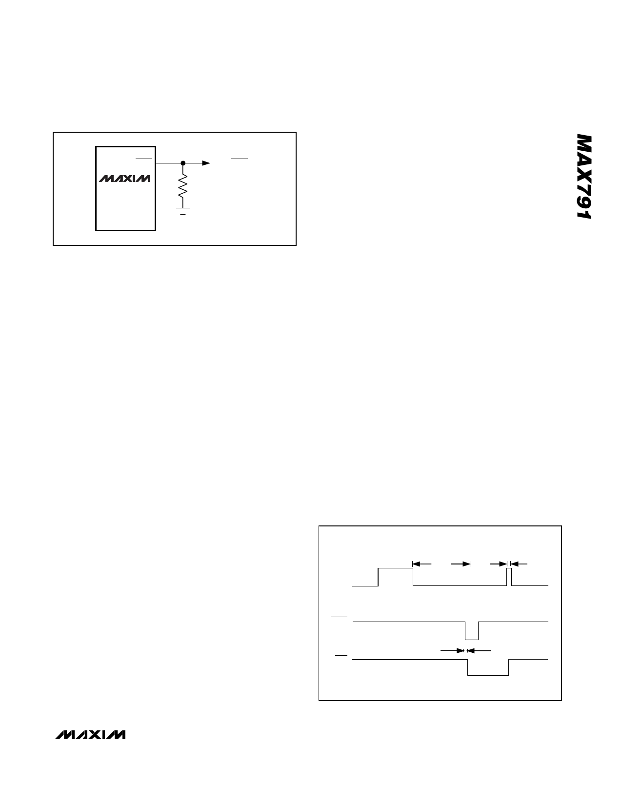
RESET
MAX791
TO µP RESET
10k
F–—i—g—u—re– 4. Adding an External Pull-Down Resistor Ensures
RESET is Valid with VCC Down to GND
RESET Output
The MAX791’s RESET output ensures that the µP pow-
ers up in a known state, and prevents code-execution
errors during power-down or brownout conditions.
The RESET output is active low, and typically sinks
3.2mA at 0.1V saturation voltage in its active state.
When deasserted, RESET sources 1.6mA at typically
VOUT - 0.5V. When no backup battery is used, RESET
output is guaranteed to be valid down to VCC = 1V, and
an external 10kΩ pull-down resistor on RESET ensures
that RESET will be valid with VCC down to GND (Figure
4). As VCC goes below 1V, the gate drive to the RESET
output switch reduces accordingly, increasing the
rDS(ON) and the saturation voltage. The 10kΩ pull-down
resistor ensures the parallel combination of switch plus
resistor is around 10kΩ and the output saturation volt-
age is below 0.4V while sinking 40µA. When using a
10kΩ external pull-down resistor, the high state for the
RESET output with VCC = 4.75V is 4.5V typ. For battery
voltages ≥ 2V connected to VBATT, RESET remains
valid for VCC from 0V to 5.5V.
RESET will be asserted during the following conditions:
• VCC < 4.65V (typ).
• MR < 1.25V (typ).
• RESET remains asserted for 200ms (typ) after VCC
rises above 4.65V or after MR has exceeded
1.25V.
The MAX791 battery-switchover comparator does not
affect RESET assertion. However, RESET is asserted in
battery-backup mode since VCC must be below the
reset threshold to enter this mode.
Watchdog Function
The watchdog monitors µP activity via the Watchdog
Input (WDI). If the µP becomes inactive, WDO and
WDPO are asserted. To use the watchdog function,
connect WDI to a bus line or µP I/O line. If WDI remains
high or low for longer than the watchdog timeout period
(1.6s nominal), WDPO and WDO are asserted, indicat-
ing a software fault condition (see Watchdog Output
and Watchdog-Pulse Output sections).
Watchdog Input
A change of state (high to low, low to high, or a mini-
mum 100ns pulse) at WDI during the watchdog period
resets the watchdog timer. The watchdog default time-
out is 1.6s. Select alternative timeout periods by con-
necting an external capacitor from SWT to GND (see
Selecting an Alternative Watchdog Timeout Period sec-
tion).
To disable the watchdog function, leave WDI floating.
An internal resistor network (100kΩ equivalent imped-
ance at WDI) biases WDI to approximately 1.6V.
Internal comparators detect this level and disable the
watchdog timer. When VCC is below the reset thresh-
old, the watchdog function is disabled and WDI is dis-
connected from its internal resistor network, thus
becoming high impedance.
Watchdog Output
WDO remains high if there is a transition or pulse at
WDI during the watchdog-timeout period. The watch-
dog function is disabled and WDO is a logic high when
VCC is below the reset threshold, battery-backup mode
is enabled, or WDI is an open circuit. In watchdog
mode, if no transition occurs at WDI during the watch-
dog-timeout period, WDO goes low 70ns after the
falling edge of WDPO and remains low until the next
transition at WDI (Figure 5). A flip-flop can force the
system into a hardware shutdown if there are two suc-
cessive watchdog faults (Figure 6). WDO has a 2 x TTL
output characteristic.
WDI
WDPO
WDO
100ns MIN
1.6s
70ns
–——– –———–
Figure 5. WDI, WDO, and WDPO Timing Diagram (VCC Mode)
_______________________________________________________________________________________ 9
Share Link: 