STOD13ASTPUR 查看數據表(PDF) - STMicroelectronics
零件编号
产品描述 (功能)
生产厂家
STOD13ASTPUR Datasheet PDF : 25 Pages
| |||
Pin configuration
2
Pin configuration
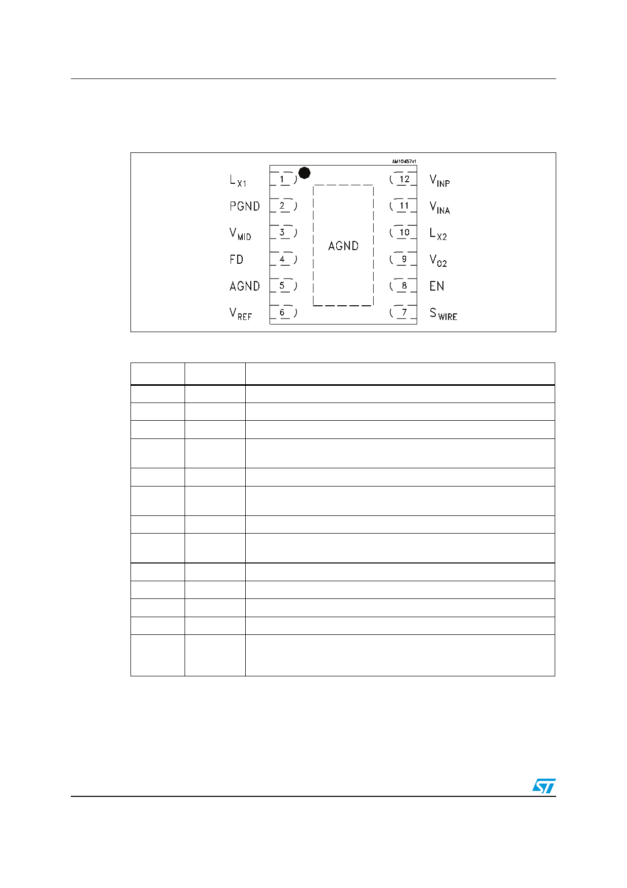
Figure 3. Pin configuration (top view)
STOD13AS
Table 3. Pin description
Pin name Pin n°
Description
Lx1
PGND
VMID
FD
AGND
VREF
SWIRE
EN
VO2
Lx2
VIN A
VIN P
1
2
3
4
5
6
7
8
9
10
11
12
Exposed
pad
Boost converter switching node
Power ground pin
Boost converter output voltage
Fast discharge control pin. When pulled LOW, the fast discharge after
shutdown is active. When pulled HIGH, the fast discharge is OFF
Signal ground pin. This pin must be connected to the power ground layer
Voltage reference output. 1 µF bypass capacitor must be connected
between this pin and AGND
Negative voltage setting pin
Enable control pin. High = converter on; Low = converter in shutdown
mode
Inverting converter output voltage
Inverting converter switching node
Analogic input supply voltage
Power input supply voltage
Internally connected to AGND. Exposed pad must be connected to
ground layers in the PCB layout in order to guarantee proper operation of
the device
6/25
Doc ID 022733 Rev 1
Share Link: 