M41T256YMT7 查看數據表(PDF) - STMicroelectronics
零件编号
产品描述 (功能)
生产厂家
M41T256YMT7 Datasheet PDF : 27 Pages
| |||
M41T256Y
DC AND AC PARAMETERS
This section summarizes the operating and mea-
surement conditions, as well as the DC and AC
characteristics of the device. The parameters in
the following DC and AC Characteristic tables are
derived from tests performed under the Measure-
Table 6. DC and AC Measurement Conditions
Parameter
VCC Supply Voltage
Ambient Operating Temperature
Load Capacitance (CL)
Input Rise and Fall Times
Input Pulse Voltages
Input and Output Timing Ref. Voltages
ment Conditions listed in the relevant tables. De-
signers should check that the operating conditions
in their projects match the measurement condi-
tions when using the quoted parameters.
M41T256Y
4.5 to 5.5V
–25 to 70°C
100pF
≤ 50ns
0.2VCC to 0.8VCC
0.3VCC to 0.7VCC
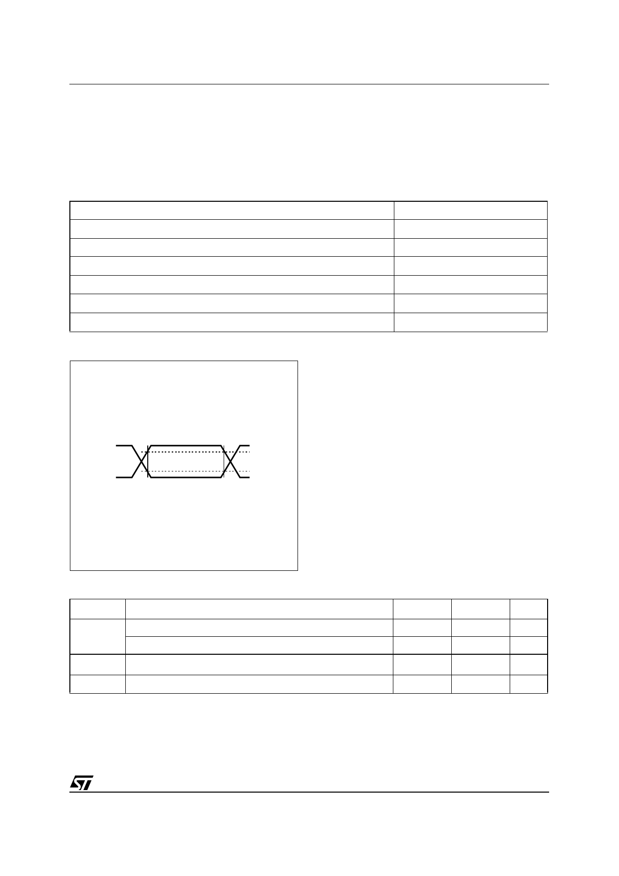
Figure 16. AC Testing Input/Output Waveforms
0.8VCC
0.2VCC
0.7VCC
0.3VCC
AI02568
Table 7. Capacitance
Symbol
Parameter(1,2)
Min
Input Capacitance
CIN
Input Capacitance (Tamper Pin)
CIO(3) Input / Output Capacitance
tLP
Low-pass filter input time constant (SDA and SCL)
Note: 1. Effective capacitance measured with power supply at 5V; sampled only, not 100% tested.
2. At 25°C, f = 1MHz.
3. Outputs deselected.
Max
Unit
7
pF
1000
pF
10
pF
50
ns
19/27
Share Link: 