GRM219R11E474JA88D 查看數據表(PDF) - Murata Manufacturing
零件编号
产品描述 (功能)
生产厂家
GRM219R11E474JA88D Datasheet PDF : 30 Pages
| |||
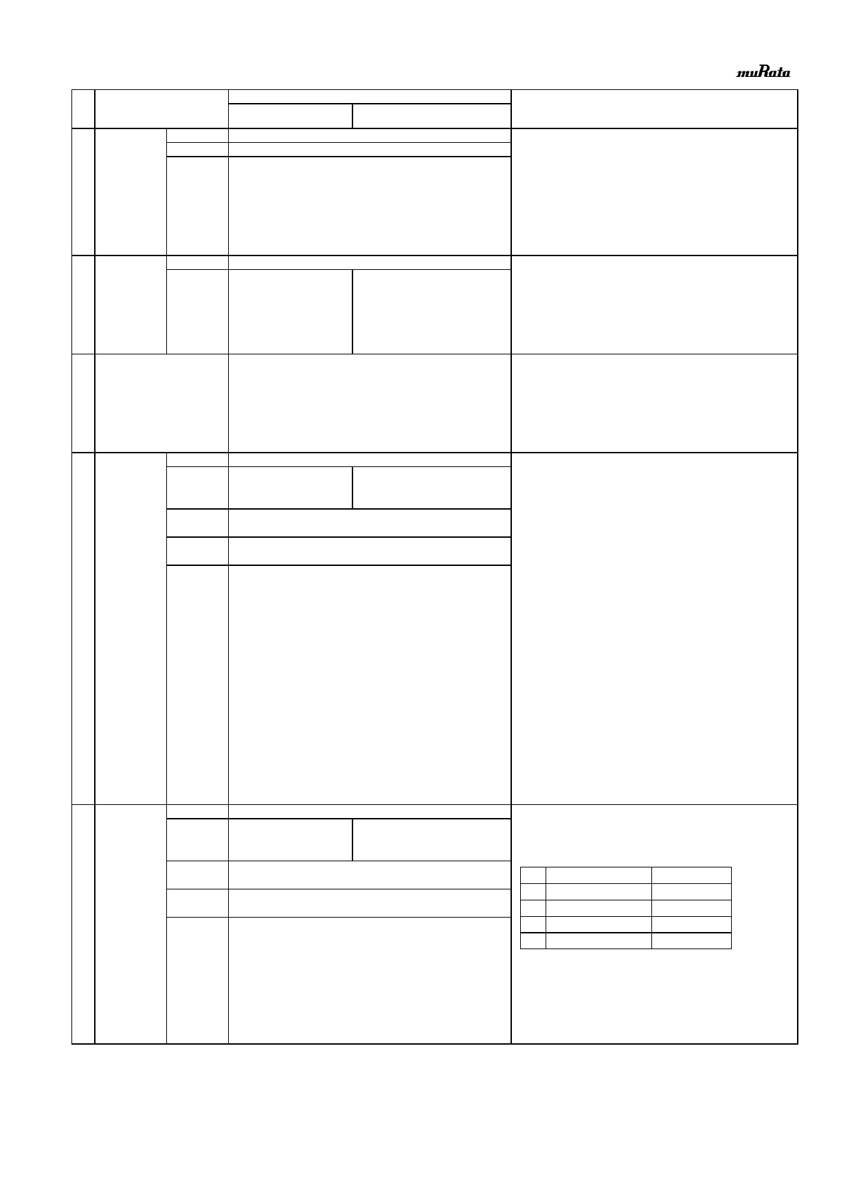
No
10 Vibration
Item
Appearance
Capacitance
Q or D.F.
Specification
Temperature
Compensating Type
High Dielectric
Constant Type
No defects or abnormalities.
Within the specified initial value.
Within the specified initial value.
Test Method
(Ref. Standard:JIS C 5101, IEC60384)
Solder the capacitor on the test substrate shown in Fig.3.
Kind of Vibration
: A simple harmonic motion
10Hz to 55Hz to 10Hz (1min)
Total amplitude
: 1.5mm
This motion should be applied for a period of 2h in each 3 mutually
perpendicular directions(total of 6h).
11 Substrate
Bending test
Appearance
Capacitance
Change
No defects or abnormalities.
Within +/-5% or +/-0.5pF
(Whichever is larger)
Within +/-10%
Solder the capacitor on the test substrate shown in Fig.1.
Pressurization method : Shown in Fig.2
Flexure
: 1mm
Holding Time
: 5+/-1s
Soldering Method
: Reflow soldering
12 Solderability
95% of the terminations is to be soldered evenly and continuously.
Test Method
Flux
Preheat
Solder
Solder Temp.
Immersion time
: Solder bath method
Solution of rojin ethanol 25(wt)%
: 80℃ to 120℃ for 10s to 30s
: Sn-3.0Ag-0.5Cu
: 245+/-5℃
: 2+/-0.5s
13 Resistance to
Soldering Heat
Appearance
Capacitance
Change
No defects or abnormalities.
Within +/-2.5% or +/- 0.25pF
(Whichever is larger)
Within +/-7.5%
Q or D.F.
Within the specified initial value.
I.R.
Within the specified initial value.
Voltage proof No defects.
<GRM03 size min.>
Test Method
: Solder bath method
Solder
: Sn-3.0Ag-0.5Cu
Solder Temp.
: 270+/-5℃
Immersion time
: 10+/-0.5s
Exposure Time
: 24+/-2h
Preheat
: GRM31 size max.: 120℃ to 150℃ for 1 min
GRM32 size : 100℃ to 120℃ for 1 min
and 170℃ to 200℃ for 1 min
· Initial measurement for high dielectric constant type
Perform a heat treatment at 150+0/-10°C for 1h and then
let sit for 24+/-2h at room temperature, then measure.
<GRM02 size only>
Test Method
: Reflow soldering (hot plate)
Solder
: Sn-3.0Ag-0.5Cu
Solder Temp.
: 270+/-5℃
Reflow Time
: 10+/-0.5s
Test Substrate
: Glass epoxy PCB
Exposure Time
: 24+/-2h
Preheat
: 120℃ to 150℃ for 1 min
· Initial measurement for high dielectric constant type
Perform a heat treatment at 150+0/-10°C for 1h and then
let sit for 24+/-2h at room temperature, then measure.
14 Temperature Appearance
Sudden Change Capacitance
Change
No defects or abnormalities.
Within +/-2.5% or+/- 0.25pF
(Whichever is larger)
Within +/-7.5%
Q or D.F.
Within the specified initial value.
I.R.
Within the specified initial value.
Voltage proof No defects.
Solder the capacitor on the test substrate shown in Fig.3.
Perform the five cycles according to the four heat treatments
shown in the following table.
Step
Temp.(C)
1 Min.Operating Temp.+0/-3
2
Room Temp.
3 Max.Operating Temp.+3/-0
4
Room Temp
Time (min)
30+/-3
2 to 3
30+/-3
2 to 3
Exposure Time
: 24+/-2h
· Initial measurement for high dielectric constant type
Perform a heat treatment at 150+0/-10°C for 1h and then
let sit for 24+/-2h at room temperature, then measure.
JEMCGS-0001U
3
Share Link: 