MCD310-14IO1_17 查看數據表(PDF) - IXYS CORPORATION
零件编号
产品描述 (功能)
生产厂家
MCD310-14IO1_17 Datasheet PDF : 6 Pages
| |||
MCD310-14io1
Thyristor
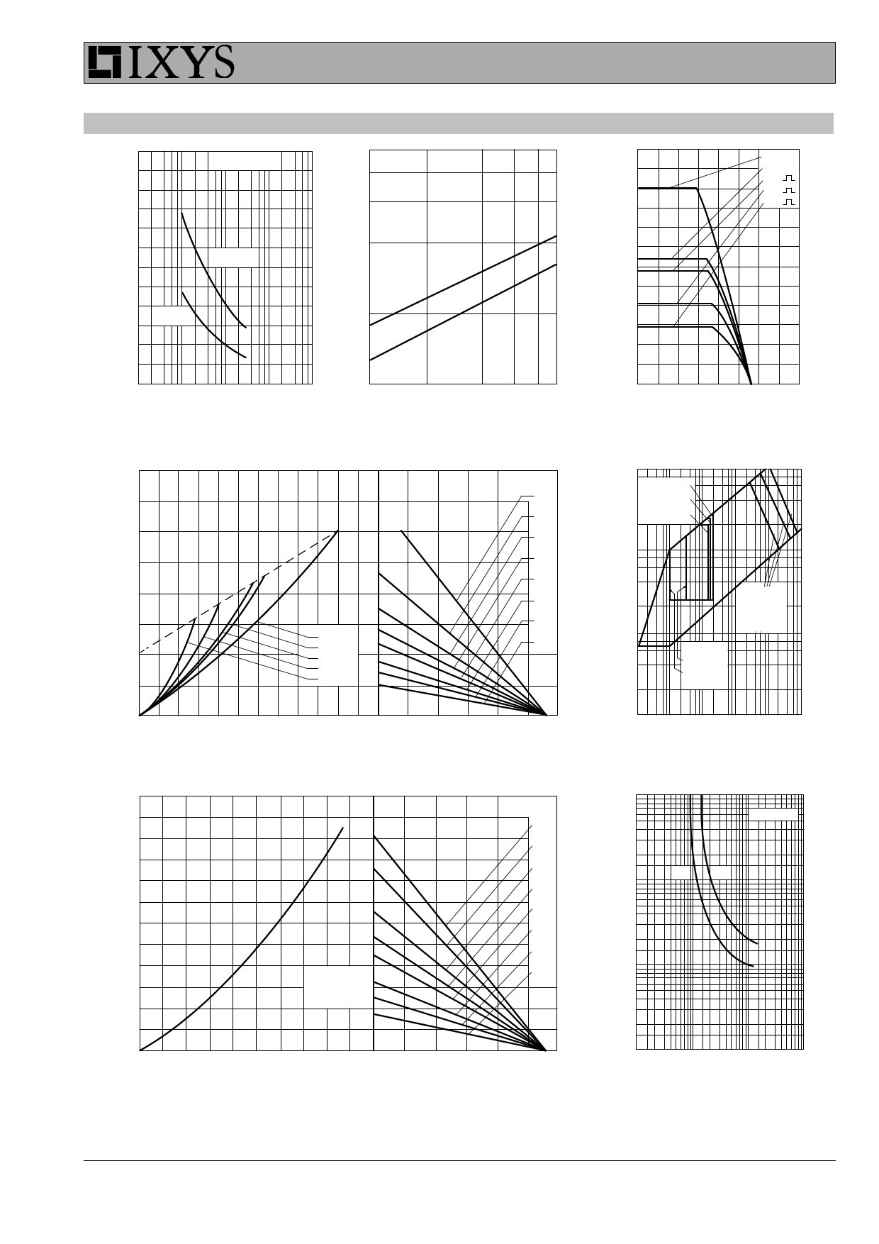
12000
10000
50 Hz, 80% VRRM
8000
ITSM
IFSM 6000
[A]
4000
TVJ = 140°C
TVJ = 45°C
2000
106
VR = 0 V
I2t
[A2s]
TVJ = 45°C
TVJ = 140°C
600
500
400
ITAVM
300
[A]
200
100
DC
180° sin
120°
60°
30°
0
10-3
10-2
10-1
100
101
t [s]
Fig. 1 Surge overload current
IT(F)SM: crest value, t: duration
105
1
2
3
t [ms]
6 8 10
Fig. 2 I2t versus time (1-10 ms)
800
600
PT
400
[W]
200
DC
180° sin
120°
60°
30°
RthJA
[K/W]
0.2
0.3
0.4
0.5
0.6
0.8
1
1.4
0
0
50
100 150 200
TC [°C]
Fig. 3 Max. forward current
at case temperature
10
IGT: TVJ = -40°C
IGT: TVJ = 0°C
IGT: TVJ = 25°C
1
VG
3
2
1
[V]
0.1
1: PGAV = 20W
2: PGAV = 60W
3: PGAV = 120W
IGD:
TVJ = 25°C
TVJ = 125°C
0
0
100 200 300 400 500
0
50
ITAVM, IFAVM [A]
Fig. 4 Power dissipation versus onstate current and•
ambient temperature (per thyristor/diode)
3000
2500
2000
PT
1500
[W]
1000
500
Circuit
B6
3x MCC310 or
3x MCD310
100
150
TA [°C]
RthKA
[K/W]
0.03
0.04
0.06
0.08
0.1
0.15
0.2
0.3
0.01
0.001 0.01
0.1 1
IG [A]
10 150
Fig. 5 Gate trigger characteristics
100
TVJ = 25°C
100
tgd
[µs]
100
typ.
Limit
0
0
200
400
600
800
0
50
100
150
IdAVM [A]
TA [°C]
Fig. 6 Three phase rectifier bridge: Power dissipation versus
direct output current and ambient temperature
100
0.01
0.1
1
10
IG [A]
Fig. 7 Gate trigger delay time
IXYS reserves the right to change limits, conditions and dimensions.
© 2017 IXYS all rights reserved
Data according to IEC 60747and per semiconductor unless otherwise specified
20170116c
Share Link: 