MAX822(1999) жҹҘзңӢж•ёж“ҡиЎЁпјҲPDFпјү - Maxim Integrated
йӣ¶д»¶зј–еҸ·
дә§е“ҒжҸҸиҝ° (еҠҹиғҪ)
з”ҹдә§еҺӮ家
MAX822
(Rev.:1999)
(Rev.:1999)
Maxim Integrated

MAX822 Datasheet PDF : 8 Pages
| |||
4-Pin ВөP Voltage Monitors with Pin-Selectable
Power-On Reset Timeout Delay
_______________Detailed Description
Reset Output
A microprocessorвҖҷs (ВөPвҖҷs) reset input starts the ВөP in a
known state. These ВөP supervisory circuits assert reset
to prevent code-execution errors during power-up,
power-down, or brownout conditions. They also provide
a reset timeout delay that is pin programmable to 1ms
(max), 20ms (min), or 100ms (min). This feature allows
flexibility in designing bar-code scanners, hand-held
devices, and other applications that require quick or
nonstandard power-up times.
The MAX821вҖҷs RESET output is guaranteed to be a
logic low for VCC > 1V. Once VCC exceeds the reset
threshold, an internal timer keeps RESET low for the
reset timeout period, as determined by the Set Reset
Timeout (SRT) input. See the Setting the Reset Timeout
Delay section.
If a brownout condition occurs (VCC dips below the
reset threshold), RESET goes low. Any time VCC goes
below the reset threshold, the internal timer resets to
zero, and RESET goes low. The internal timer begins
counting after VCC returns above the reset threshold,
and RESET remains low for the reset timeout period.
The MAX822 has an active-high RESET output that is
the inverse of the MAX821вҖҷs RESET output.
Setting the Reset Timeout Delay
Use the three-level Set Reset Timeout (SRT) input to set
the reset timeout delay. Connect SRT to GND for a 1ms
(max) delay; connect it to VCC for a 20ms (min) delay;
or leave it unconnected for a 100ms (min) delay.
If you choose to drive the SRT pin with an external sig-
nal, make sure the signal source can charge/discharge
the capacitance on SRT quickly enough (<500Вөs) to
avert an unintended reset timeout delay.
To ensure proper operation when selecting the 100ms
timeout (SRT = unconnected), minimize capacitive
loading on the SRT pin (< 200pF). Excessive capacitive
loading can select an unintended faster timeout mode.
Reset Threshold Accuracy
The MAX821/MAX822 are designed to meet their worst-
case specifications over their entire operating tempera-
ture range. Choose a reset threshold guaranteed to
assert at a voltage below the power supplyвҖҷs regulation
range and above the minimum specified operating volt-
age range for the systemвҖҷs ICs.
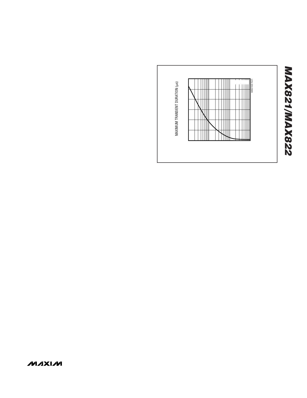
300
TA = +25В°C
250
200
150
100
50
0
1
10
100
1000
RESET COMPARATOR OVERDRIVE, VTH-VCC (mV)
Figure 1. Maximum Transient Duration Without Causing a
Reset Pulse vs. Comparator Overdrive
__________Applications Information
Negative-Going VCC Transients
While designed to issue a reset to the microprocessor
(ВөP) during power-up, power-down, and brownout con-
ditions, the MAX821/MAX822 are relatively immune to
short-duration, negative-going VCC transients (glitches).
Figure 1 shows the maximum transient duration vs. reset
comparator overdrive for which the MAX821/MAX822
typically do not generate a reset pulse. This graph was
generated using a negative-going pulse applied to VCC,
starting above the actual reset threshold and ending
below it by the magnitude indicated (reset comparator
overdrive). The graph indicates the typical maximum
pulse width a negative-going VCC transient may have
without causing a reset pulse to be issued. As the mag-
nitude of the transient increases (goes farther below the
reset threshold), the maximum allowable pulse width
decreases. Typically, for the MAX821/MAX822, a VCC
transient that goes 100mV below the reset threshold and
lasts 12Вөs or less will not cause a reset pulse to be
issued. A 0.1ВөF capacitor mounted as close as possible
to VCC can provide additional transient immunity, if
desired.
_______________________________________________________________________________________ 5
Share Link: