MC68HC000R8 查看數據表(PDF) - Motorola => Freescale
零件编号
产品描述 (功能)
生产厂家
MC68HC000R8 Datasheet PDF : 26 Pages
| |||
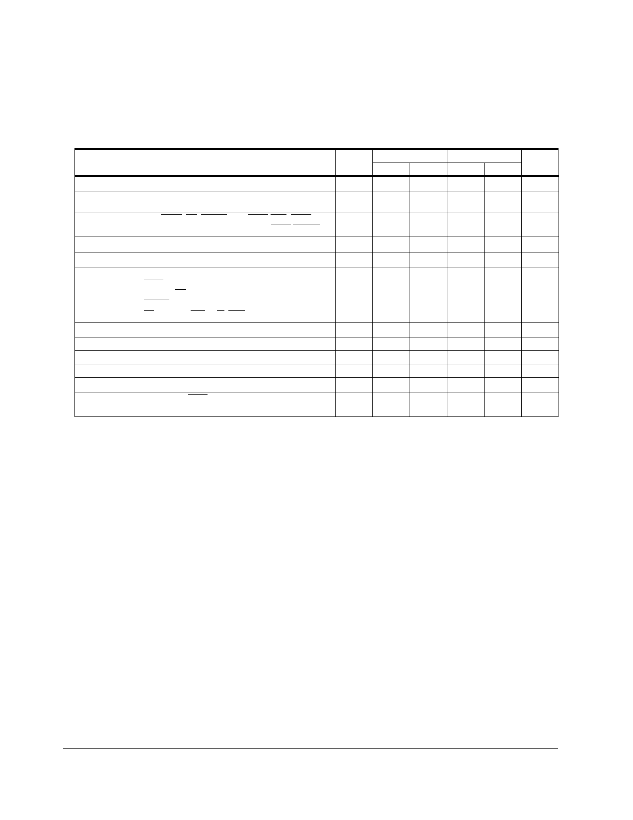
5.0 MC68SEC000 DC ELECTRICAL SPECIFICATIONS
Add the following table to Section 10.13 on page 10-23.
(VCC = 5.0 Vdc ±5%, 3.3 Vdc ±10%,; GND = 0 Vdc; TA = TL to TH)
3.3 V
5.0 V
CHARACTERISTIC
SYMBOL MIN MAX MIN MAX UNIT
Input High Voltage
VIH
2.0
VCC
2.0
VCC
V
Input Low Voltage
VIL
GND
0.8 GND – 0.8
0.5
V
Input Leakage Current BERR, BR, DTACK, CLK, I PL2-IPL0, AVEC
Iin
—
2.5
—
2.5
uA
MODE, HALT, RESET
20
20
Three-State (Off State) Input Current
ITSI
—
2.5
—
2.5
uA
Output High Voltage
VOH
2.4
— VCC–0.75 —
V
Output Low Voltage
(IOL = 1.6 mA) HALT
(IOL = 3.2 mA) A23–A0, BG, FC2–FC0
(IOL = 5.0 mA) RESET
(IOL = 5.3 mA) AS, D15–D0, LDS, R/W, UDS
VOL
V
—
0.5
—
0.5
—
0.5
—
0.5
—
0.5
—
0.5
—
0.5
—
0.5
Current Dissipation*
f = 0 Hz
ID
—
0.7
—
1.0
mA
f=10MHz
—
10
—
15
mA
f=16 MHz
—
15
—
25
mA
f= 20 MHz
—
20
—
30
mA
Capacitance (Vin = 0 V, TA = 25 °C, Frequency = 1 MHz)**
Cin
—
20.0
—
20.0
pF
Load Capacitance
HALT
All Others
CL
—
70
—
70
pF
130
130
*During normal operation, instantaneous Vcc current requirements may be as high as 1.5A.
Currents listed are with no loading.
**Capacitance is periodically sampled rather than 100% tested.
10
M68000 USER’S MANUAL ADDENDUM
MOTOROLA
Share Link: 