B8NM60(2005) жҹҘзңӢж•ёж“ҡиЎЁпјҲPDFпјү - STMicroelectronics
йӣ¶д»¶зј–еҸ·
дә§е“ҒжҸҸиҝ° (еҠҹиғҪ)
з”ҹдә§еҺӮ家
B8NM60
(Rev.:2005)
(Rev.:2005)
STMicroelectronics

B8NM60 Datasheet PDF : 16 Pages
| |||
STP8NM60 - STP8NM60FP - STD5NM60 - STD5NM60-1 - STB8NM60 - STB8NM60
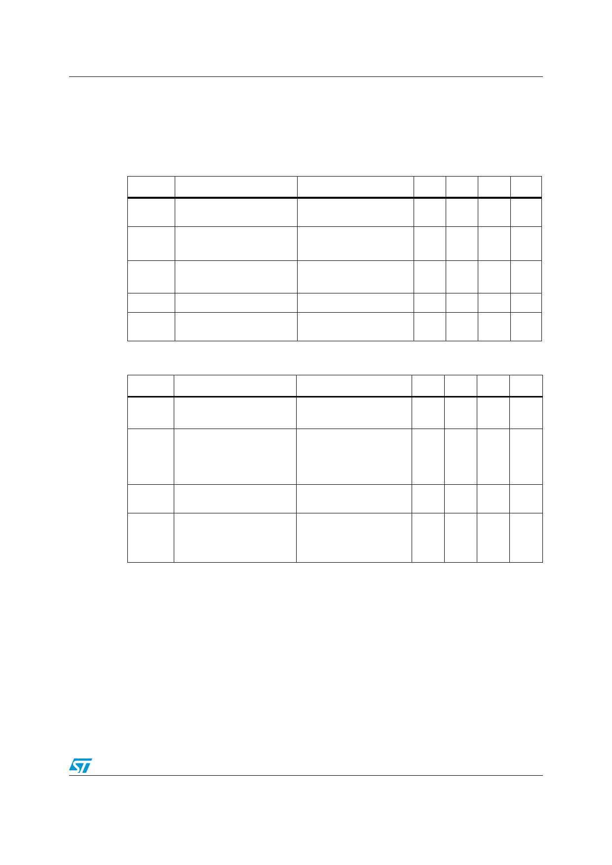
ELECTRICAL CHARACTERISTICS (CONTINUED)
Table 7: Dynamic
Symbol
Parameter
gfs
Forward Transconductance
Ciss
Coss
Crss
Coss eq. (2)
td(on)
tr
Input Capacitance
Output Capacitance
Reverse Transfer
Capacitance
Equivalent Output
Capacitance
Turn-on Delay Time
Rise Time
Qg
Total Gate Charge
Qgs
Gate-Source Charge
Qgd
Gate-Drain Charge
Test Conditions
VDS = ID(on) x RDS(on)max,
ID = 2.5A
VDS = 25V, f = 1 MHz, VGS = 0
Min.
VGS = 0V, VDS = 0V to 480V
VDD = 300 V, ID = 2.5 A
RG = 4.7в„Ұ VGS = 10 V
(Resistive Load see, Figure 3)
VDD = 400V, ID = 5 A,
VGS = 10V
Table 8: Switching On/Off
Symbol
Parameter
td(off)
tf
Turn-off Delay Time
Fall Time
tr(Voff)
tf
tc
Off-voltage Rise Time
Fall Time
Cross-over Time
Test Conditions
VDD = 300 V, ID = 2.5 A
RG = 4.7в„Ұ VGS = 10 V
(Resistive Load see, Figure 3)
VDD = 480V, ID = 5 A,
RG = 4.7в„Ұ, VGS = 10V
(Inductive Load see, Figure 5)
Table 9: Source Drain Diode
Symbol
Parameter
Test Conditions
ISD
ISDM ( )
Source-drain Current
Source-drain Current (pulsed)
VSD (2) Forward On Voltage
ISD = 5 A, VGS = 0
trr
Qrr
IRRM
Reverse Recovery Time
Reverse Recovery Charge
Reverse Recovery Current
ISD = 5 A, di/dt = 100A/Вөs
VDD = 100 V, Tj = 25В°C
(see test circuit, Figure 5)
trr
Qrr
IRRM
Reverse Recovery Time
Reverse Recovery Charge
Reverse Recovery Current
ISD = 5 A, di/dt = 100A/Вөs
VDD = 100 V, Tj = 150В°C
(see test circuit, Figure 5)
(2) Pulsed: Pulse duration = 300 Вөs, duty cycle 1.5 %.
Min.
Min.
Typ.
2.4
440
100
10
50
14
10
13
5
6
Max. Unit
S
pF
pF
pF
pF
ns
ns
18 nC
nC
nC
Typ.
23
10
7
10
17
Max.
Unit
ns
ns
ns
ns
ns
Typ.
300
1950
13
445
3005
13.5
Max. Unit
8
A
32
A
1.5
V
ns
ВөC
A
ns
ВөC
A
3/16
Share Link: