SAM4S 查看數據表(PDF) - Atmel Corporation
零件编号
产品描述 (功能)
生产厂家
SAM4S Datasheet PDF : 67 Pages
| |||
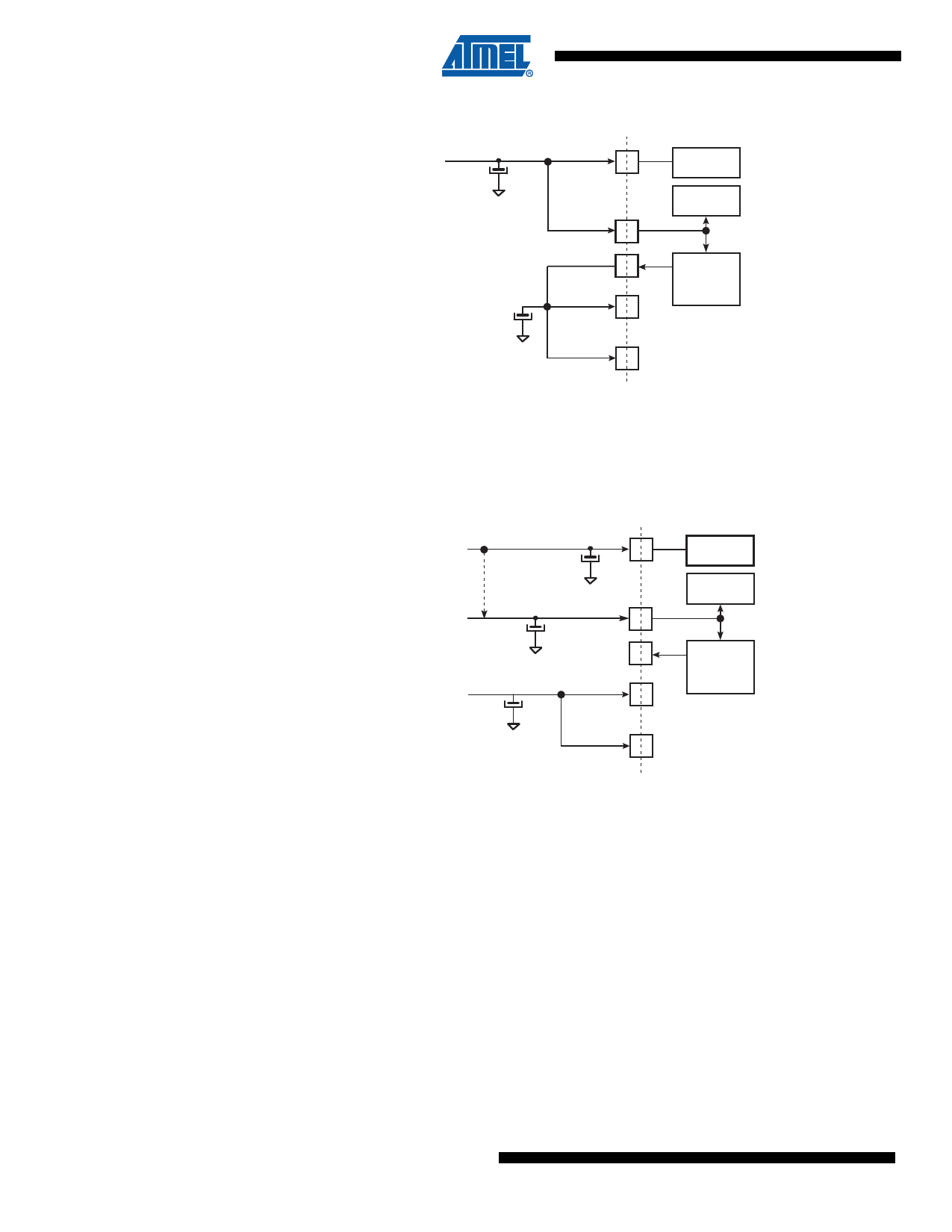
Figure 5-1. Single Supply
Main Supply
(1.8V-3.6V)
VDDIO
VDDIN
VDDOUT
VDDCORE
VDDPLL
USB
Transceivers.
ADC, DAC
Analog Comp.
Voltage
Regulator
Note:
Restrictions
For USB, VDDIO needs to be greater than 3.0V.
For ADC, VDDIN needs to be greater than 2.0V.
For DAC, VDDIN needs to be greater than 2.4V.
Figure 5-2.
Core Externally Supplied
Main Supply
(1.62V-3.6V)
VDDIO
Can be the
same supply
ADC, DAC, Analog
Comparator Supply
(2.0V-3.6V)
VDDCORE Supply
(1.08V-1.32V)
VDDIN
VDDOUT
VDDCORE
VDDPLL
USB
Transceivers.
ADC, DAC
Analog Comp.
Voltage
Regulator
Note:
Restrictions
For USB, VDDIO needs to be greater than 3.0V.
For ADC, VDDIN needs to be greater than 2.0V.
For DAC, VDDIN needs to be greater than 2.4V.
Figure 5-3 below provides an example of the powering scheme when using a backup battery.
Since the PIO state is preserved when in backup mode, any free PIO line can be used to switch
off the external regulator by driving the PIO line at low level (PIO is input, pull-up enabled after
backup reset). External wake-up of the system can be from a push button or any signal. See
Section 5.6 “Wake-up Sources” for further details.
20 SAM4S Series [Preliminary]
11100BS–ATARM–31-Jul-12
Share Link: 