TS925 查看數據表(PDF) - STMicroelectronics
零件编号
产品描述 (功能)
生产厂家
TS925 Datasheet PDF : 17 Pages
| |||
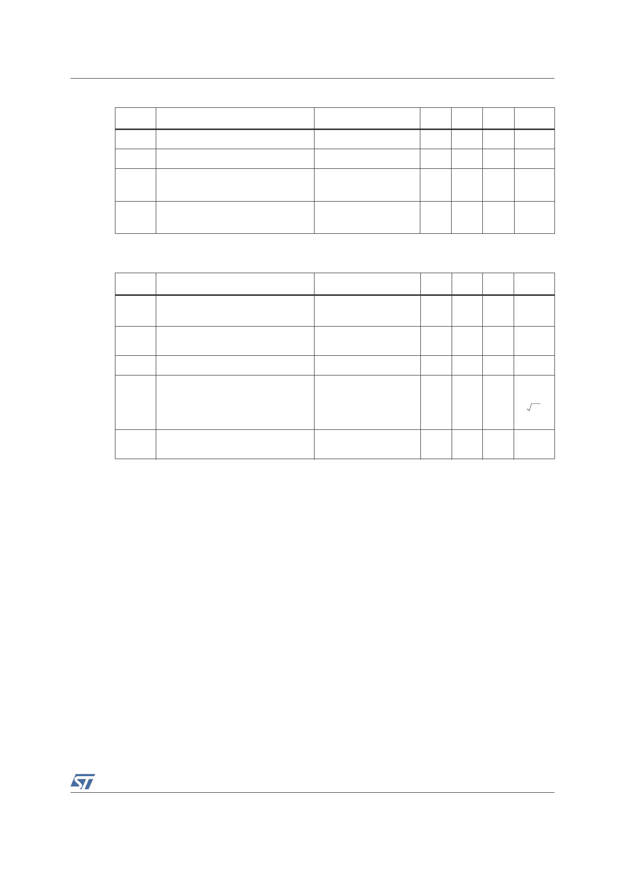
TS925
Electrical Characteristics
Table 4.
Symbol
Global circuit
Parameter
Conditions
Min. Typ Max. Unit
ICC Total Supply Current
No load, Vout = Vcc/2
5
7
mA
Istby Total Supply Current in STANDBY Pin 9 connected to Vcc-
6
µA
Venstby Pin 9 Voltage to enable the
STANDBY mode (1)
at Tamb = +25°C
at Tmin ≤ Tamb ≤ Tmax
0.3
0.4
V
Vdistby Pin 9 Voltage to disable the
STANDBY mode(1)
at Tamb = +25°C
1.1
at Tmin ≤ Tamb ≤ Tmax
1
V
1. The STANDBY mode is currently enabled when Pin 9 is GROUNDED and disabled when Pin 9 is left OPEN.
Table 5.
Symbol
Phantom ground
Parameter
Vpg Phantom Ground Output Voltage
Ipgsc
Zpg
Enpg
Phantom Ground Output Short
Circuit Current - Sourced
Phantom Ground Impedance
Phantom Ground Output Voltage
Noise
Ipgsk
Phantom Ground Output Short
Circuit Current - Sinked
1. Cdec is the decoupling capacitor on Pin9.
Conditions
No Output Current
DC to 20kHz
f = 1kHz
Cdec = 100pF
Cdec = 1nF
Cdec = 10nF(1)
Min. Typ Max.
Vcc/2 Vcc/2 Vcc/2
-5%
+5%
Unit
V
12 18
mA
3
Ω
200
---n---V-----
40
Hz
17
12 18
mA
5/17
Share Link: 