AN1045 查看數據表(PDF) - STMicroelectronics
零件编号
产品描述 (功能)
生产厂家
AN1045 Datasheet PDF : 16 Pages
| |||
ST7 S/W IMPLEMENTATION OF I2C BUS MASTER
1.1 COMMUNICATION SPEED
The communication speed is modifiable by using the function delay(time) which waits for a
given time period and then modifies the frequency of SCL.
Here Fscl is equal to 62.5 kHz. It can be easily reduced by increasing the period between two
clock cycles, but this speed is not far from the highest speed you can have (~70 kHz).
1.2 START, STOP CONDITION AND ACKNOWLEDGE GENERATION
The Start and Stop conditions are always generated by the master. In this software, there are
no bits to set to generate these conditions like in the real peripheral: you just have to call the
corresponding function (I2Cm_Start() and I2Cm_Stop()).
An Acknowledge is sent after an address or a data byte is received. When the master has to
receive an acknowledge from the slave, you have to call the function Wait_Ack() which reads
the SDA and SCL lines to recognize the acknowledge condition (the SDA line put at the low
state by the one which sends the acknowledge during one clock pulse). And when the master
has to send an acknowledge after receiving data from the slave, you have to call the function
I2Cm_Ack().
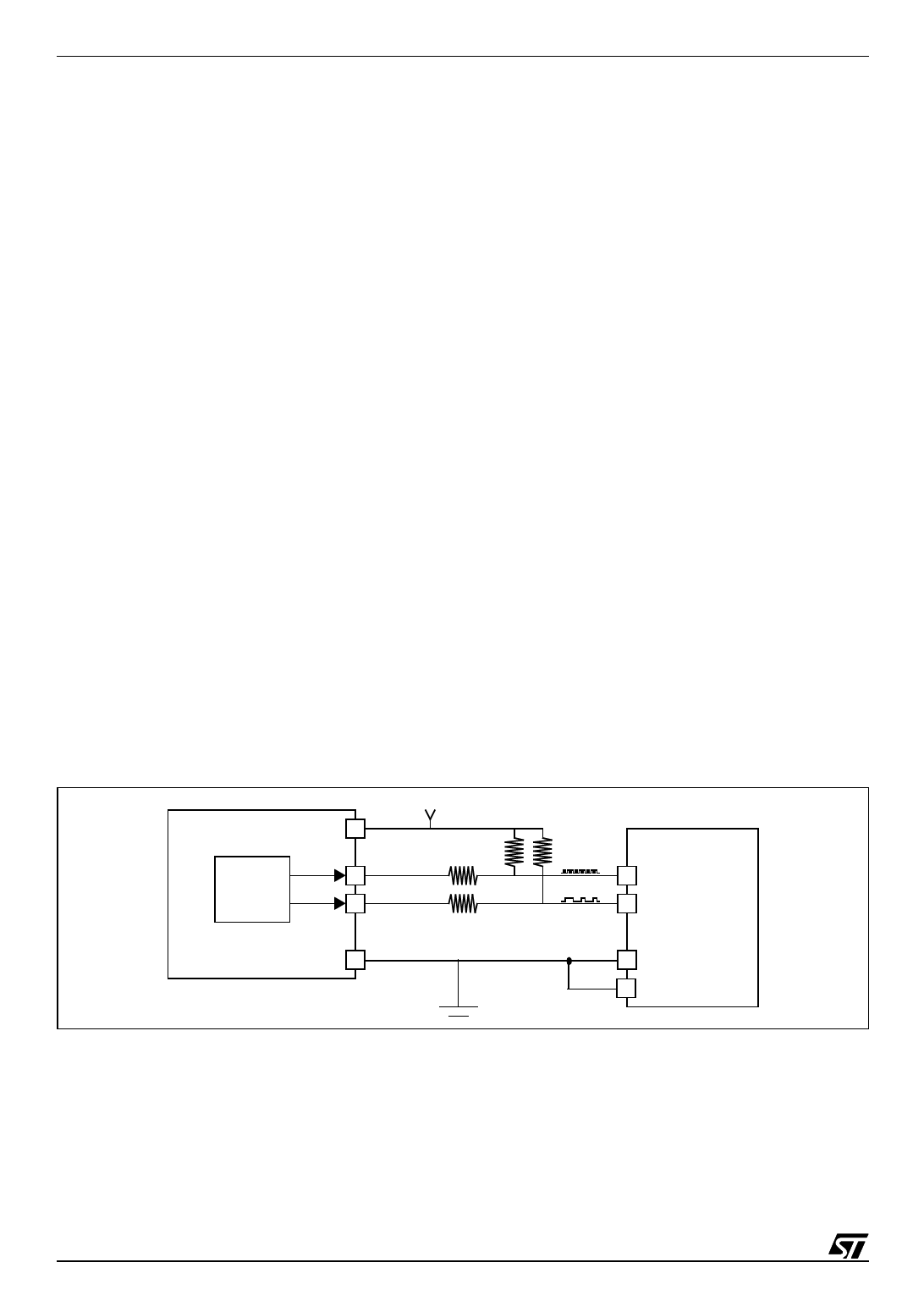
2 ST7 I2C COMMUNICATION APPLICATION
2.1 HARDWARE CONFIGURATION
The ST7 communication application hardware is composed of a ST72324 microcontroller
(which has no I2C peripheral) and any slave (an M24C08 EEPROM for example).
Figure 1. ST7 / E2PROM I2C Communication Application
ST72324 Vdd
SCL
I2C SDA
Vss
5V
2x100W
2x12KW
M24C08
SCL
SDA
Vss
E
2/16
2
Share Link: 