IP100A 查看數據表(PDF) - Unspecified
零件编号
产品描述 (功能)
生产厂家
IP100A Datasheet PDF : 97 Pages
| |||
IP100A LF
Preliminary Data Sheet
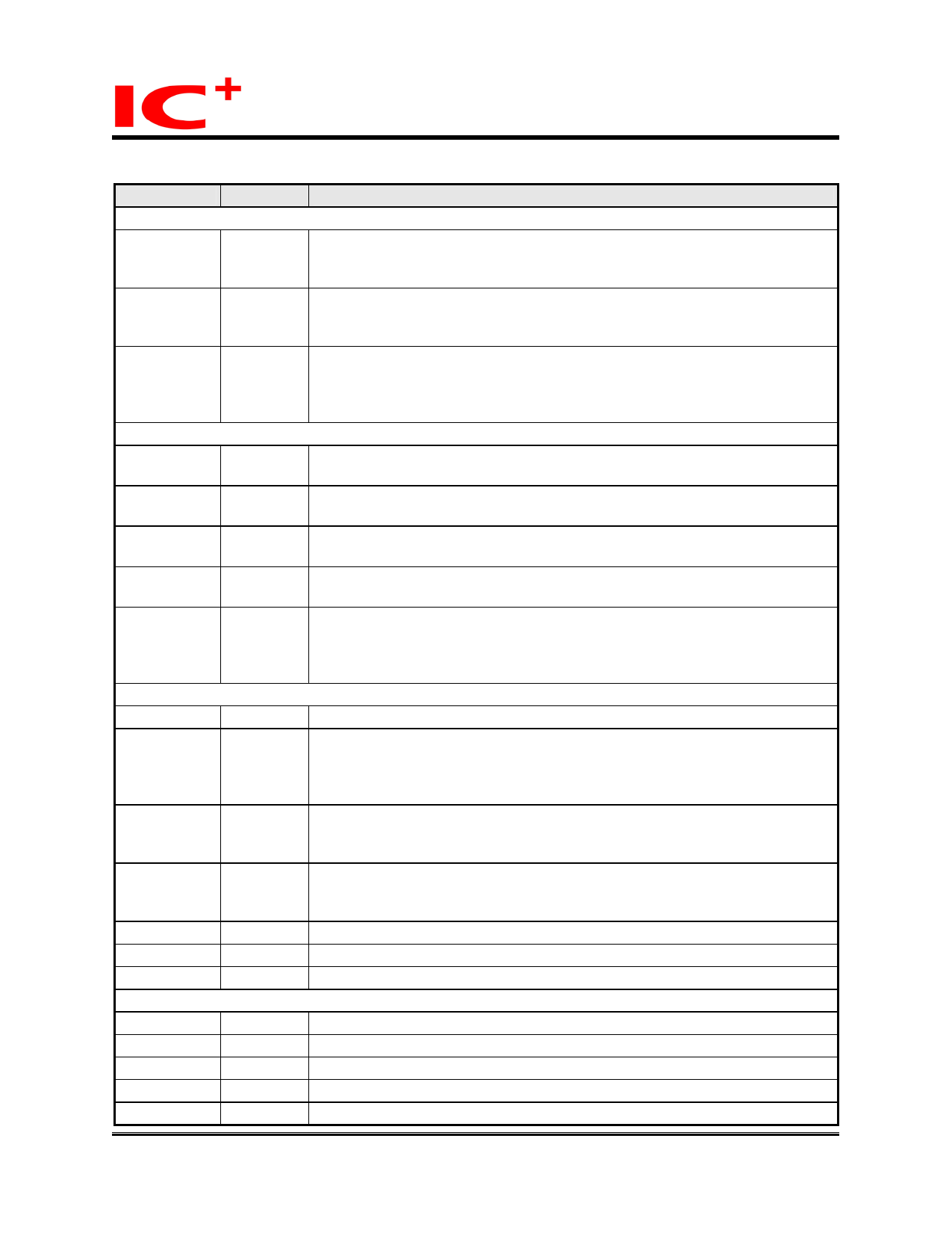
PIN Descriptions (continued)
PIN NAME PIN TYPE
PIN DESCRIPTION
LED DRIVERS (continued)
LED_10N
OUTPUT
10Mb/sec Connection Status LED. This pin will output LOW to indicate
10Mb/sec Transmission if the connection between 2 devices have
negoatiated to link at 10Mb/sec.
LED_100N
OUTPUT
100Mb/sec Connection Status LED. This pin will output LOW to indicate
100Mb/sec Transmission if the connection between 2 devices have
negoatiated to link at 100Mb/sec.
LED_LINK
OUTPUT
Link Status LED. LED_LINK is the link status LED driver. The functionality
of the link status LED signal is based on the LEDMode bit of the AsicCtrl
register. A 4.7K pull-down resistor is placed between this pin and GND
regardless of whether the LED is connected to this pin.
MDI
RXP
INPUT
Receive input. When in 100BASE-TX mode, this receives MLT3 data from
the isolation transformer. When in 100BASE-FX mode, this is a PECL input.
RXN
INPUT
Receive input. When in 100BASE-TX mode, this receives MLT3 data from
the isolation transformer. When in 100BASE-FX mode, this is a PECL input.
TXP
OUTPUT Transmit output. When in 100BASE-TX mode, this is an MLT-3 driver.
When in 100BASE-FX mode, this is a PECL driver.
TXN
OUTPUT Transmit output. When in 100BASE-TX mode, this is an MLT-3 driver.
When in 100BASE-FX mode, this is a PECL driver.
FFSD
INPUT
This pin is used to select TP or Fiber mode. For 100BASE-FX applications,
FFSD is connected to the signal detect output pin of a fiber optic module at
PECL level. Connecting this pin to GND will force the IP100A into TP
mode.
MISCELLANEOUS
CTRL25
OUTPUT This is a controller pin to monitor correct 2.5V supply to IC.
LAST_GASPN INPUT
This pin monitors the PCI voltage. If the voltage is dropped to certain value,
LAST_GASPN will indicate IP100A LF to transmit LAST GASP frame to inform
the other end that IP100A LF is not functioning till SYSTEM POWER ON or
RESET.
X1
OSCIN 25MHz Crystal Oscillator Input. The external 25MHz crystal and capacitor
is connected to the on-chip crystal oscillator circuit through X1 input.
Alternately, X1 can be driven by an external clock source.
X2
OSCOUT 25MHz Crystal Oscillator Output. The external crystal and capacitor is also
connected to the output of the on-chip crystal oscillator circuit through X2.
When X1 is driven by an external clock source, X2 should be left unconnected.
ISET
ANALOG Band Gap Resistor. Connect a 6.2kohm, 1% resister between ISET and GND.
TEST
INPUT
Test. Enables the IP100A LF test modes.
NC
Reserved. These Pins must keep floating at application circuit.
POWER AND GROUND
VCC2
POWER +3.3 volt I/O power supply.
VCC1
POWER +2.5 volt digital logic power supply.
AVCC25
POWER +2.5 volt analog power supply.
AVCC33
POWER +3.3 volt analog power supply.
AVSS
GROUND Analog Ground
Copyright © 2004, IC Plus Corp.
11/97
March. 30, 2007
IP100A LF-DS-R17
Share Link: 