LC72708E 查看數據表(PDF) - SANYO -> Panasonic
零件编号
产品描述 (功能)
生产厂家
LC72708E Datasheet PDF : 15 Pages
| |||
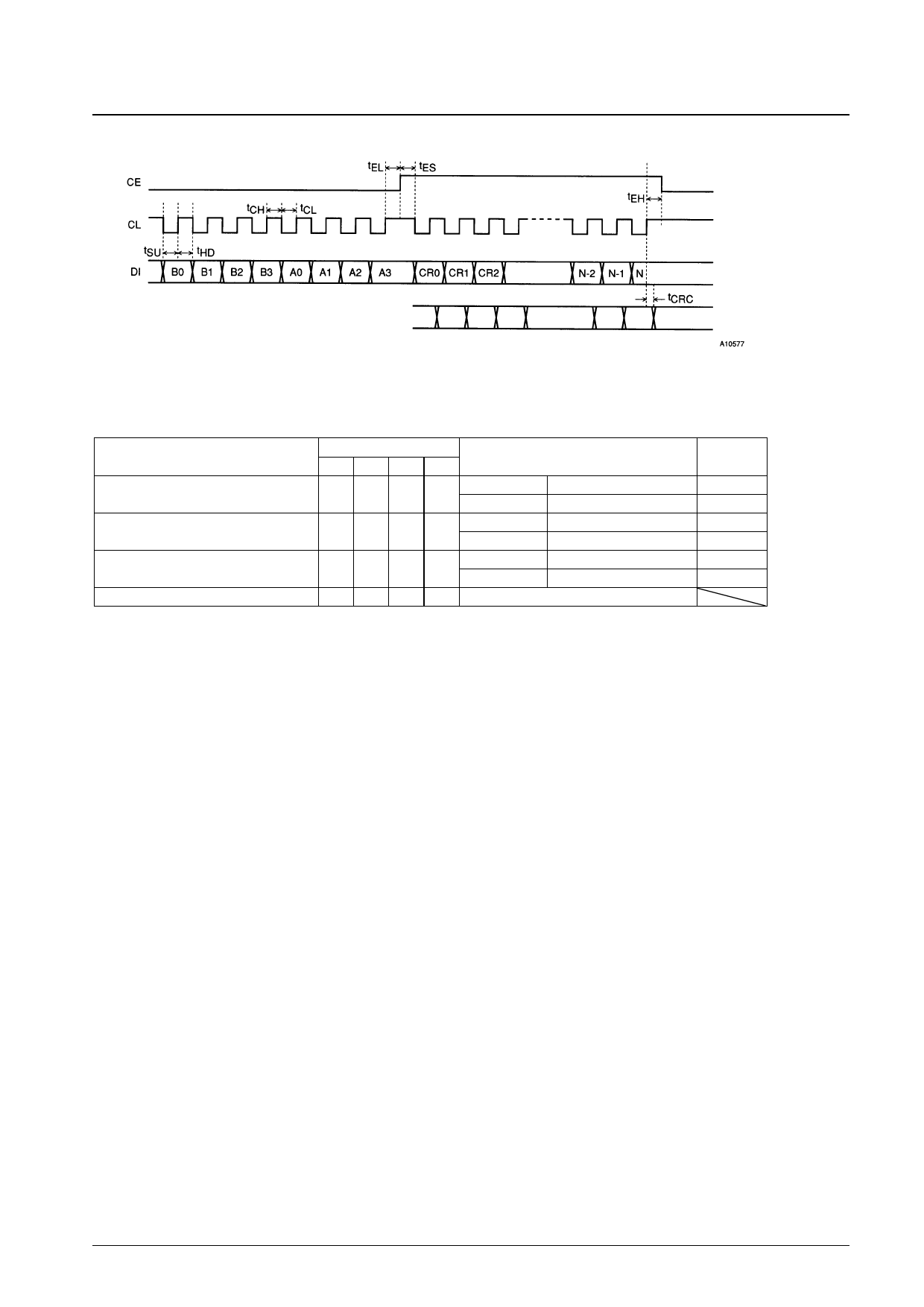
• Layer 4 CRC Data Input Timing
LC72708E
CRC4 pin output
Note: The N items are 8-bit units.
CRC4 output after N items transferred
Serial Control Data Input Settings
The input data consists of 16 bits (DI0 to DI15). The upper 8 bits (DI8 to DI15) are the control address and the lower 8
bits (DI0 to DI7) are the input data. Bits DI12 to DI15 are ignored.
Register
Number of allowable BIC errors
Number of block error protection states
Number of frame error protection states
Control register
Address
DI11 DI10 DI9 DI8
Data
Upper 4 bits Allowed error bits backward
0
0
0
0
Lower 4 bits Allowed error bits forward
Upper 4 bits Block backward protection
0
0
0
1
Lower 4 bits Block forward protection
Upper 4 bits Frame backward protection
0
0
1
0
Lower 4 bits Frame forward protection
0
0
1
1 See the control register description on page 8.
Default
setting
2
2
1
7
1
7
• Number of Allowed BIC Errors
This IC’s synchronization circuit operates by recognizing a 16-bit BIC code. The number of allowed errors is the
number of allowed error bits in the 16 bits used for BIC recognition. This data item allows the forward protection mode
(used when synchronized) and the backward protection mode (used when not synchronized) values to be set
independently. The default value is to allow up to 2 error bits in both the forward and backward directions. We
recommend setting the backward protection mode number of allowable BIC errors to 1 or 0 if the block
synchronization recognition output (the BLOCK pin, pin 23) is used to recognize the presence or absence of FM
multiplex data.
• Block Synchronization Error Protection Count
The synchronization protection count can be set independently in the forward and backward directions. The protection
count conditions are as follows.
— Backward protection (unsynchronized, BLOCK = low)
When the timing of the IC’s internal synchronization free-running counter matches that of the received BIC, the
protection count is incremented by 1. Similarly, if the IC internal counter and the received BIC do not match, the
counter is cleared to 0. The count timing is the timing of the IC internal counter.
— Forward protection (synchronized, BLOCK = high)
Operation is the opposite of the backward case, namely, the protection count is incremented when the timing of the
IC’s internal synchronization free-running counter does not match that of the received BIC, and the protection
count is cleared to zero when the timing matches.
Figure 1 shows the protection counter when both the forward and backward protection counts are set to 3.
This IC defines the protection counter value to be 1 at the point where a match or a mismatch occurs between the IC
internal timing and the received BIC timing. For example, a backward protection count of 2 corresponds to the case
where the IC internal timing and the received BIC timing match two times consecutively. To set the protection data to
new values, applications must send data in which 1 has been subtracted from the desired values, e.g. to set up protection
counts of 3 as shown in figure 1, applications must send the value 22H. Similarly, if the value set is 00, due to the
definition, the protection counts for both the forward and backward directions will be set to 1. However, from an
operation standpoint, this corresponds to operation equivalent to there being no protection circuit. The default values are
a forward protection count of 8 and a backward protection count of 2. We recommend resetting the block synchronization
Continued on next page.
No. 5875-6/15
Share Link: 