MSM6242B 查看數據表(PDF) - Oki Electric Industry
零件编号
产品描述 (功能)
生产厂家
MSM6242B Datasheet PDF : 18 Pages
| |||
MSM6242B
¡ Semiconductor
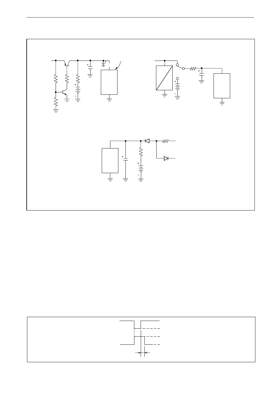
TYPICAL APPLICATION — POWER SUPPLY CIRCUIT
VCE (SAT.) = 0.1V
+5V
RIPPLE
OPERATING: 20mV P-P
BATTERY BACKUP: 0mV
22µf 4.7µf
VDD
51K 10K 100Ω
MSM
6242B
1.2 x 3 = 3.6V
Ni – Cd
VSS
10K
Figure 19.
RL
+5V
RL
M
C 100Ω
B
1.5 x 2 = 3V
DRY CELLS
4.7µf
VDD
MSM
6242B
VSS
Figure 20.
VDD
MSM
6242B
VSS
220Ω
~ 6.5V
100Ω
D1
4.7µf
RL
+5V
1.2 x 3 = 3.6V
Ni – Cd
Figure 21.
4.7µF: tantalum
SUPPLEMENTARY DESCRIPTION
• When "0" is written to the IRQ FLAG bit, the IRQ FLAG bit is cleared. However, if "0" is
assigned to the IRQ FLAG bit when written to the other bits, the 30-sec ADJ bit and the
HOLD bit, the IRQ FLAG = 1 and was generated before the writing and IRQ FLG = 1
generated in a moment then will be cleared. To avoid this, always set "1" to the IRQ
FLAG unless "0" is written to it intentionally. By writing "1" to it, the IRQ FLAG bit
does not become "1".
• Since the IRQ FLAG bit becomes "1" in some cases when rewriting either of the t1, t0, or
ITRPT/STND bit of register CE, be sure to write "0" to the IRQ FLAG bit after writing to
make valid the IRQ FLAG = 1 to be generated after it.
* The relationship between SDT.P OUT and IRQ FLAG bit is shown below:
STD.P OUT
IRQ FLAG bit
open
"L"
1
0
approx. 1.95 ms
40
Share Link: 