MAX9720 查看數據表(PDF) - Maxim Integrated
零件编号
产品描述 (功能)
生产厂家
MAX9720 Datasheet PDF : 21 Pages
| |||
50mW, DirectDrive, Stereo Headphone
Amplifier with SmartSense and Shutdown
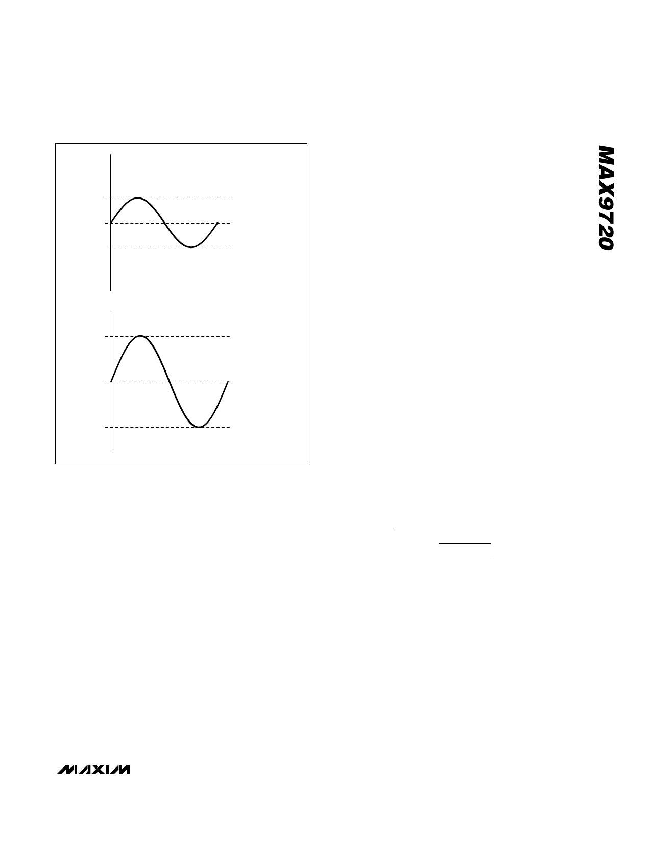
VOUT
VDD
VDD/2
GND
CONVENTIONAL DRIVER-BIASING SCHEME
+VDD
VOUT
GND
-VDD
DirectDrive BIASING SCHEME
Figure 1. Conventional Amplifier Output Waveform vs.
MAX9720 Output Waveform
DirectDrive
Conventional single-supply headphone amplifiers have
their outputs biased about a nominal DC voltage (typical-
ly half the supply) for maximum dynamic range. Large
coupling capacitors are needed to block this DC bias
from the headphone. Without these capacitors, a signifi-
cant amount of DC current flows to the headphone,
resulting in unnecessary power dissipation and possible
damage to both headphone and headphone amplifier.
Maxim’s patented DirectDrive architecture uses a
charge pump to create an internal negative supply volt-
age. This allows the MAX9720 output to be biased
about GND, almost doubling dynamic range while
operating from a single supply. With no DC component,
there is no need for the large DC-blocking capacitors.
Instead of two large capacitors (220µF typ), the
MAX9720 charge pump requires only two, small ceram-
ic capacitors (1µF typ), conserving board space,
reducing cost, and improving the frequency response
of the headphone amplifier. See the Output Power vs.
Charge-Pump Capacitance and Load Resistance
graph in the Typical Operating Characteristics for
details of the possible capacitor sizes.
Previous attempts to eliminate the output-coupling
capacitors involved biasing the headphone return
(sleeve) to the DC bias voltage of the headphone
amplifiers. This method raised some issues:
• The sleeve is typically grounded to the chassis.
Using this biasing approach, the sleeve must be
isolated from system ground, complicating product
design.
• During an ESD strike, the amplifier’s ESD structures
are the only path to system ground. The amplifier
must be able to withstand the full ESD strike.
• When using the headphone jack as a line out to
other equipment, the bias voltage on the sleeve
may conflict with the ground potential from other
equipment, resulting in large ground-loop current
and possible damage to the amplifiers.
• When using a combination microphone and speak-
er headset (in a cell phone or PDA application), the
microphone typically requires a GND return. Any
DC bias on the sleeve conflicts with the microphone
requirements (Figure 2).
Low-Frequency Response
In addition to the cost and size disadvantages, the DC-
blocking capacitors limit the low-frequency response of
the amplifier and distort the audio signal:
• The impedance of the headphone load and the DC-
blocking capacitor form a highpass filter with the
-3dB point determined by:
f−3dB
=
1
2πRLCOUT
where RL is the impedance of the headphone and
COUT is the value of the DC-blocking capacitor.
The highpass filter is required by conventional single-
ended, single-supply headphone amplifiers to block
the midrail DC component of the audio signal from the
headphones. Depending on the -3dB point, the filter
can attenuate low-frequency signals within the audio
band. Larger values of COUT reduce the attenuation,
but are physically larger, more expensive capacitors.
Figure 3 shows the relationship between the size of
COUT and the resulting low-frequency attenuation. Note
that the -3dB point for a 16Ω headphone with a 100µF
blocking capacitor is 100Hz, well within the audio
band.
______________________________________________________________________________________ 11
Share Link: 