MB95FV100D-103PBT 查看數據表(PDF) - Fujitsu
零件编号
产品描述 (功能)
生产厂家
MB95FV100D-103PBT Datasheet PDF : 74 Pages
| |||
MB95160M Series
• Mode Pin (MOD)
Connect the MOD pin directly to VCC or VSS.
To prevent the device unintentionally entering test mode due to noise, lay out the printed circuit board so as to
minimize the distance from the MOD pin to VCC or VSS and to provide a low-impedance connection.
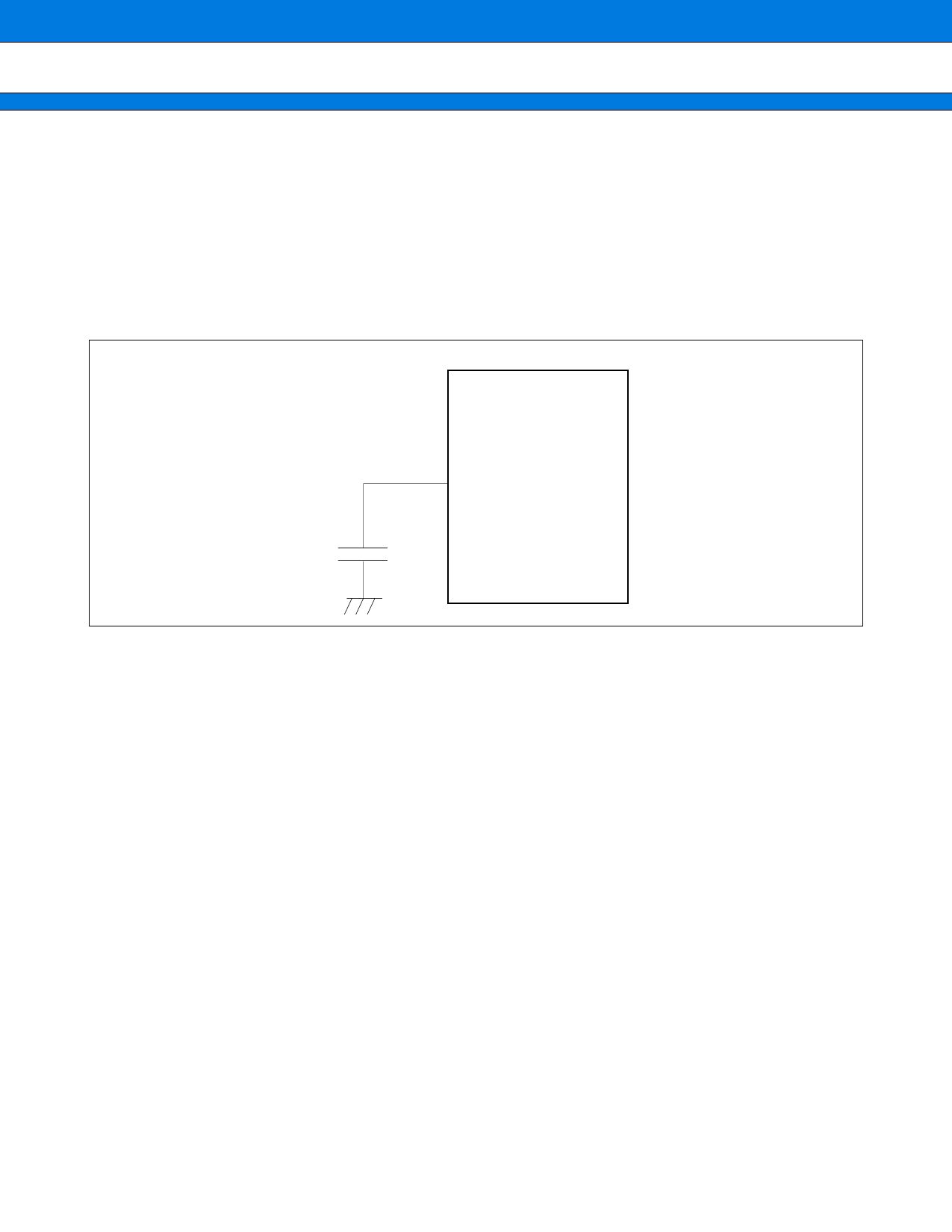
Use a ceramic capacitor or a capacitor with equivalent frequency characteristics. A bypass capacitor of VCC pin
must have a capacitance value higher than CS. For connection of smoothing capacitor CS, refer to the diagram
below.
• C pin connection diagram
C
CS
• Analog Power Supply
Always set the same potential to AVCC and VCC pins. When VCC > AVCC, the current may flow through the AN00
to AN07 pins.
• Treatment of Power Supply Pins on A/D Converter
Connect to be AVCC = VCC and AVSS = AVR = VSS even if the A/D converter is not in use.
Noise riding on the AVCC pin may cause accuracy degradation. So, connect approx. 0.1 µF ceramic capacitor
as a bypass capacitor between AVCC and AVSS pins in the vicinity of this device.
15
Share Link: 