MCP1612T-ADJI/MF(2005) 查看數據表(PDF) - Microchip Technology
零件编号
产品描述 (功能)
生产厂家
MCP1612T-ADJI/MF Datasheet PDF : 22 Pages
| |||
MCP1612
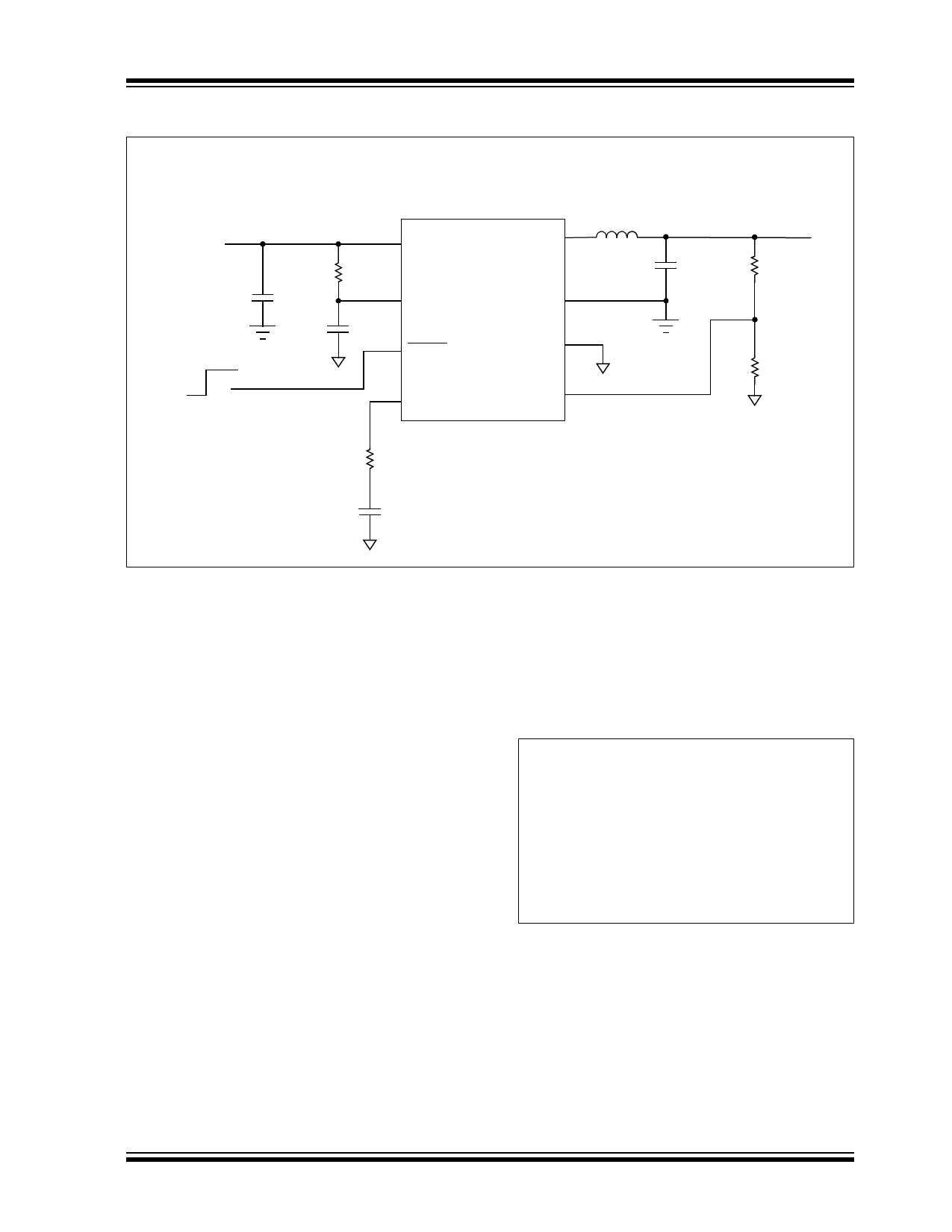
5.0 APPLICATION CIRCUITS/INFORMATION
MCP1612 3.3V to 1.2V Synchronous Buck Converter
3.3VIN ±10%
CIN
10 µF
Ceramic
ON
OFF
CBYP
0.1 µF
Ceramic
1
VIN
MCP1612
10Ω
8 L = 3.3 µH
Lx
2
VCC
7
PGND
3
SHDN
6
AGND
4
Comp
5
FB
1.2V VOUT @ 1A
COUT
10 µF
Ceramic
100 kΩ
200 kΩ
25 kΩ
1000 pF
FIGURE 5-1:
Typical Application Circuit.
5.1 Typical Applications
The MCP1612 buck controller can be used in several
different applications where a voltage that is lower than
the supply voltage is required. Its small size, low cost
and high efficiency make the MCP1612 a good choice
for densely-packaged applications. The input voltage
range, low-dropout voltage and low shutdown current
make this part perfectly suited for battery-powered
applications.
5.2 Design Example
The step-by-step design of a buck converter with the
following parameters is presented to illustrate how
easy the MCP1612 is to use.
Input voltage = 3.3V
Output voltage = 1.2V
Output current = 0A to 1A
Switching frequency = 1.4 MHz
5.2.1 SETTING OUTPUT VOLTAGE
The output voltage of the MCP1612 is set by using an
external resistor-divider network. The voltage present
at FB is internally compared to a 0.8V reference
voltage. A 200 kΩ resistor is recommended for R2, the
lower-end of the voltage divider. Using higher-value
resistors will make the circuit more susceptible to noise
on the FB pin. Lower-value resistors can be used, if
necessary.
Equation 5-1, used to calculate the output voltage, is
shown below.
EQUATION 5-1:
Where:
R1
=
R2
×
⎛
⎝
V----O----U----T-
VFB
–
1⎠⎞
VOUT = desired output voltage
VFB = MCP1612 internal reference
voltage
R1 = top resistor value
R2 = bottom resistor value
For this example:
VOUT = 1.2V
VFB = 0.8V
R2 = 200 kΩ
R1 = 100 kΩ
The MCP1612 is capable of a 15% duty cycle.
Instability may result when the duty cycle is below 15%.
If less than 15% duty cycle operation is needed, care
must be taken to ensure stable operation.
© 2005 Microchip Technology Inc.
DS21921B-page 11
Share Link: 