MT312 查看數據表(PDF) - Zarlink Semiconductor Inc
零件编号
产品描述 (功能)
生产厂家
MT312 Datasheet PDF : 90 Pages
| |||
Functional Overview MT312
1.4 Forward Error Correction
The MT312 contains FEC blocks to enable error
correction for DVB-S and DSS transmissions. The
Viterbi decoder block can decode the convolutional
code with rates 1/2, 2/3, 3/4, 5/6, 6/7 or 7/8. The
block features automatic synchronisation, automatic
IQ phase resolution and automatic code rate
detection. The trace back depth of 128 provides
better performance at high code rates and the built-in
synchronisation algorithm allows the Viterbi decoder
to lock onto signals with very poor signal-to-noise
ratios. Viterbi bit error rate monitor provides an
indication of the error rate at QPSK output.
The 24-bit error count register in the Viterbi decoder
allows the bit error rate at the output of the QPSK
demodulator to be monitored. The 24-bit bit error
count register in the Reed-Solomon decoder allows
the Viterbi output bit error rate to be monitored. The
16-bit uncorrectable packet counter yields
information about the output packet error rate. These
three monitors and the QPSK SNR register allows
the performance of the device and its individual
components, such as the QPSK demodulator and
the Viterbi decoder, to be monitored extensively by
the external microprocessor.
The frame/byte align block features a sophisticated
synchronisation algorithm to ensure reliable recovery
of DVB and DSS framed data streams under worst
case signal conditions. The de-interleaver uses on-
chip RAM and is compatible with the DVB and DSS
algorithms.
The Reed-Solomon decoder is a truncated version of
the (255, 239) code. The code block size is 204 for
DVB and 146 for DSS. The decoder provides a count
of the number of uncorrectable blocks as well as the
number of bit errors corrected. The latter gives an
indication of the bit error rate at the output of the
Viterbi decoder.
In DVB mode, spectrum de-scrambling is performed
compatible with the DVB specification. The final
output is a parallel or serial transport data stream;
packet sync; data clock; and a block error signal. The
data clock may be inverted under software control.
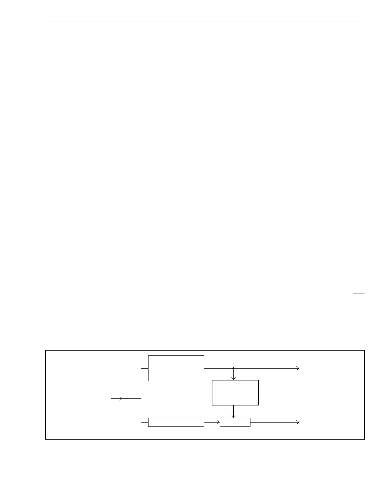
1.4.1.1 Viterbi Error Count Measurement
A method of estimating the bit error rate at the output
of the QPSK block has been provided in the Viterbi
decoder. The incoming data bit stream is delayed
and compared with the re-encoded and punctured
version of the decoded bit stream to obtain a count of
errors see Figure 4 - Viterbi block diagram.
The measurement system has a programmable
register to determine the number of data bits (the
error count period) over which the count is being
recorded. A read register indicates the error count
result and an interrupt can be generated to inform
the host microprocessor that a new count is
available.
The VIT ERRPER H-M-L group of three registers is
programmed with required number of data bits (the
error count period) (VIT ERRPER[23:0]). The actual
value is four times VIT ERRPER[23:0]. The count of
errors found during this period is loaded by the
MT312 into the VIT ERRCNT H-M-L trio of registers
when the bit count VIT ERRPER[23:0] is reached. At
the same time an interrupt is generated on the IRQ
line. Setting the IE FEC[2] bit in the IE FEC register
enables the interrupt, see page 32. Reading the
register does not clear VIT ERRCNT [23:0], it is only
loaded with the error count.
VITERBI
DECODER
DATA BIT STREAM
VITERBI
ENCODER
DELAY
COMP
ERROR COUNT
Figure 4 - Viterbi block diagram
11
Share Link: 