STK672-630A-E 查看數據表(PDF) - ON Semiconductor
零件编号
产品描述 (功能)
生产厂家
STK672-630A-E Datasheet PDF : 21 Pages
| |||
Usage Notes
STK672-630A-E
1. STK672-630A-E, STK672-640A-E input signal functions and timing
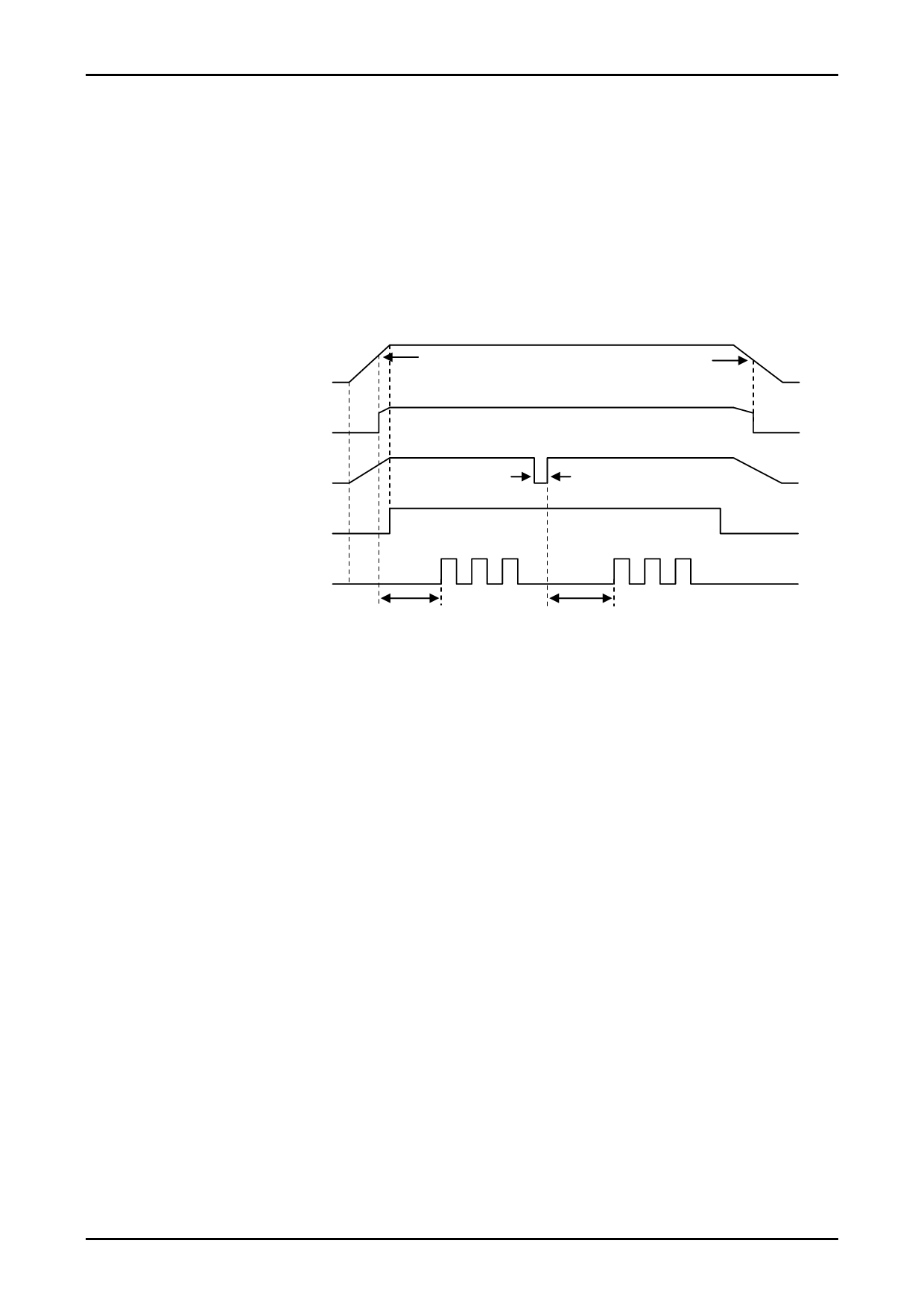
[ENABLE, CLOCK and power on reset, RESETB (Input signal timing when power is first applied)]
The control IC of the driver is equipped with a power on reset function capable of initializing internal IC operations
when power is supplied. A 4V typ setting is used for power on reset. Because the specification for the MOSFET gate
voltage is 5V±5%, conduction of current to output at the time of power on reset adds electromotive stress to the
MOSFET due to lack of gate voltage. To prevent electromotive stress, be sure to set ENABLE=Low while VDD,
which is outside the operating supply voltage, is less than 4.75V.
In addition, if the RESETB terminal is used to initialize output timing, be sure to allow at least 10μs until CLOCK
input.
Control IC power (VDD) rising edge
4V typ
3.8V typ
Control IC power on reset
RESETB signal input
No time specification
ENABLE signal input
CLOCK signal input
At least 10μs
At least 10μs
ENABLE, CLOCK, and RESETB Signals Input Timing
[CLOCK (Phase switching clock)]
• Input frequency: DC to 50kHz
• Minimum pulse width: 10μs
• MODE2=1(High) Signals are read on the rising edge.
• MODE2=0(Low) Signals are read on the rising and falling edges.
[CWB (Motor direction setting)]
The direction of rotation is switched by setting CWB to 1 (high) or 0 (low).
See the timing charts for details on the operation of the outputs.
Note: The state of the CWB input must not be changed during the 6.25μs period before and after the rising edge of the
CLOCK input.
[ENABLE (Forcible on/off control of the A, AB, B, and BB outputs, and hybrid IC internal operation)]
ENABLE=1: Normal operation
ENABLE=0: Outputs A, AB, B, and BB forced to the off state.
If, during the state where CLOCK signal input is provided, the ENABLE pin is set to 0 and then is later
restored to the 1 state, the IC will resume operation with the excitation timing continued from before the
point ENABLE was set to 0.
If sudden stop is applied to the CLOCK signal used for motor rotation, the motor axis may advance beyond the
theoretical position due to inertia. To stop at the theoretical position, the SLOW DOWN setting for gradually slowing
the CLOCK cycle is required.
No. A1129-11/21
Share Link: 