ISL83080EIB(2005) жҹҘзңӢж•ёж“ҡиЎЁпјҲPDFпјү - Intersil
йӣ¶д»¶зј–еҸ·
дә§е“ҒжҸҸиҝ° (еҠҹиғҪ)
з”ҹдә§еҺӮ家
ISL83080EIB
(Rev.:2005)
(Rev.:2005)
Intersil

ISL83080EIB Datasheet PDF : 18 Pages
| |||
ISL83080E, ISL83082E, ISL83083E, ISL83085E, ISL83086E, ISL83088E
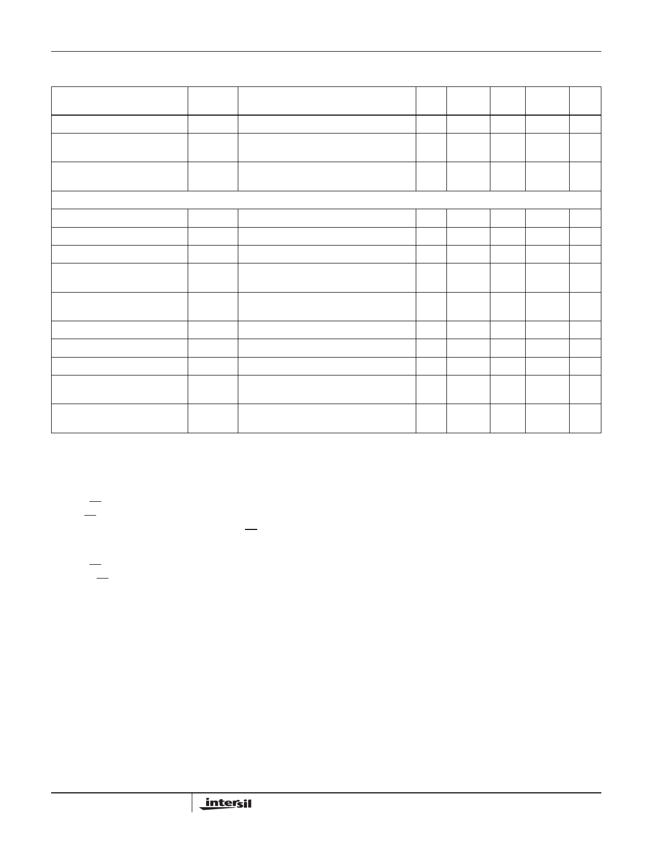
Electrical Specifications Test Conditions: VCC = 4.5V to 5.5V; Unless Otherwise Specified. Typicals are at VCC = 5V, TA = 25В°C
(Note 4) (Continued)
PARAMETER
SYMBOL
TEST CONDITIONS
TEMP
(В°C) MIN
TYP MAX UNITS
Receiver Enable to Output High
tZH
RL = 1kв„Ұ, CL = 15pF, SW = GND (Figure 6),
(Note 8)
Full
-
10
30
ns
Receiver Disable from Output Low
tLZ
RL = 1kв„Ұ, CL = 15pF, SW = VCC (Figure 6)
Receiver Disable from Output High
tHZ
RL = 1kв„Ұ, CL = 15pF, SW = GND (Figure 6)
Time to Shutdown
tSHDN (Notes 9, 12)
Receiver Enable from Shutdown to tZH(SHDN) RL = 1kв„Ұ, CL = 15pF, SW = GND (Figure 6),
Output High
(Notes 9, 11)
Full
-
10
30
ns
Full
-
10
30
ns
Full
60
160 600
ns
Full
-
150 2000 ns
Receiver Enable from Shutdown to tZL(SHDN) RL = 1kв„Ұ, CL = 15pF, SW = VCC (Figure 6),
Output Low
(Notes 9, 11)
Full
-
150 2000 ns
NOTES:
4. All currents into device pins are positive; all currents out of device pins are negative. All voltages are referenced to device ground unless
otherwise specified.
5. Supply current specification is valid for loaded drivers when DE = 0V.
6. Applies to peak current. See вҖңTypical Performance CurvesвҖқ for more information.
7. Keep RE = 0 to prevent the device from entering SHDN.
8. The RE signal high time must be short enough (typically <100ns) to prevent the device from entering SHDN.
9. Transceivers are put into shutdown by bringing RE high and DE low. If the inputs are in this state for less than 60ns, the parts are guaranteed
not to enter shutdown. If the inputs are in this state for at least 600ns, the parts are guaranteed to have entered shutdown. See вҖңLow-Power
Shutdown ModeвҖқ section.
10. Keep RE = VCC, and set the DE signal low time >600ns to ensure that the device enters SHDN.
11. Set the RE signal high time >600ns to ensure that the device enters SHDN.
12. Guaranteed by characterization but not tested.
Test Circuits and Waveforms
VCC DE
DI
Z
D
Y
VOD
RL/2
RL/2 VOC
VCC DE
DI
Z
D
Y
VOD
375в„Ұ
RL = 60в„Ұ
VCM
-7V to +12V
375в„Ұ
FIGURE 1A. VOD AND VOC
FIGURE 1B. VOD WITH COMMON MODE LOAD
FIGURE 1. DC DRIVER TEST CIRCUITS
8
FN6085.6
September 12, 2005
Share Link: