RT8120 查看數據表(PDF) - Richtek Technology
零件编号
产品描述 (功能)
生产厂家
RT8120 Datasheet PDF : 17 Pages
| |||
RT8120
LGATE Over Current Setting (LGOCS)
Over current threshold is externally programmed by adding
a resistor (ROCSET) between LGATE and GND. Once VCC
exceeds the POR threshold, an internal current source
IOCSET flows through ROCSET. The voltage across ROCSET is
stored as the over current protection threshold VOCSET.
After that, the current source is switched off. ROCSET can
be determined using the following equation :
R OCSET
=
IVALLEY x RLGDS(ON)
IOCSET
where IVALLEY represents the desired inductor OCP trip
current (valley inductor current).
If ROCSET is not present, there is no current path for IOCSET
to build the OCP threshold. In this situation, the OCP
threshold is internally preset to 375mV (typical).
Under Voltage Protection (UVP)
The voltage on the FB pin is monitored for under voltage
protection. If the FB voltage is lower than the UVP threshold
(typically 75% x VREF) during normal operation, UVP will
be triggered. When the UVP is triggered, both UGATE
and LGATE go low. The controller enters hiccup mode
until the UVP condition is removed.
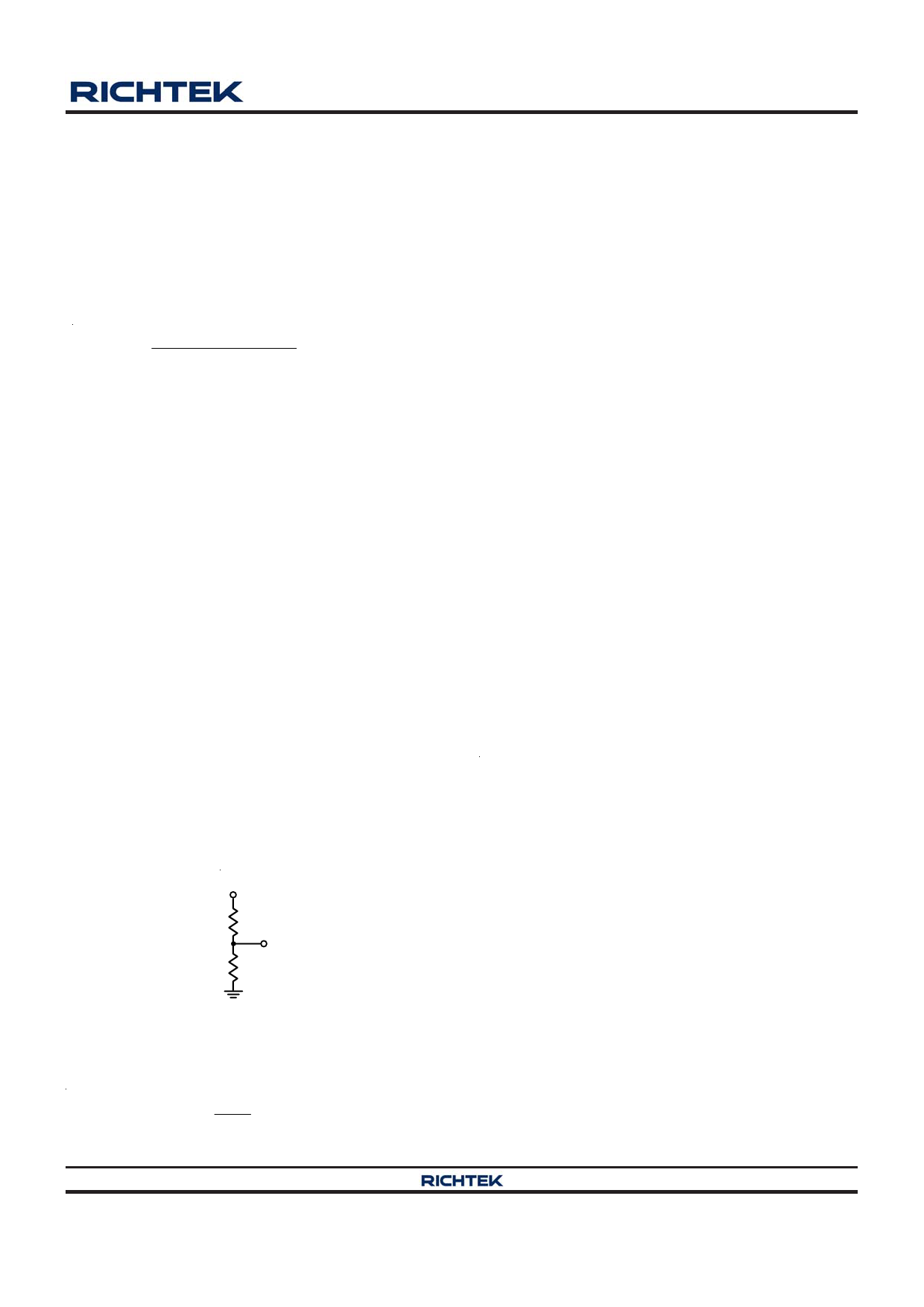
Output Voltage Setting
The RT8120 allows the output voltage of the DC/DC
converter to be adjusted from 0.8V (option for 0.6V) to
85% of VIN via an external resistor divider. It will try to
maintain the feedback pin at internal reference voltage
(0.8V, with option for 0.6V).
VOUT
RFB1
FB
RFB2
Figure 3. Output Voltage Setting
According to the resistor divider network above, the output
voltage is set as :
VOUT
= VREF
x
⎛
⎜1 +
⎝
RFB1
RFB2
⎞
⎟
⎠
MOSFET Drivers
The RT8120 integrates high current gate drivers for the
two N-MOSFETs to obtain high efficiency power conversion
in synchronous buck topology. A dead time is used to
prevent crossover conduction for the high side and low
side MOSFETs. Because both gate signals are off during
dead time, the inductor current freewheels through the
body diode of the low side MOSFET. The freewheeling
current and the forward voltage of the body diode contribute
to power loss. The RT8120 employs constant dead time
control scheme to ensure safe operation without
sacrificing efficiency. Furthermore, elaborate logic circuit
is implemented to prevent cross conduction.
For high output current applications, two or more power
MOSFETs are usually paralleled to reduce RDS(ON). The
gate driver needs to provide more current to switch on/off
these paralleled MOSFETs. Gate driver with lower source/
sink current capability result in longer rising/ falling time
in gate signals, and therefore higher switching loss.
The RT8120 embeds high current gate drivers to obtain
high efficiency power conversion. The embedded drivers
contribute to the majority of the power dissipation of the
controller. Therefore, SOP package is chosen for its power
dissipation rating. If no gate resistor is used, the power
dissipation of the controller can be approximately
calculated using the following equation :
PDRIVER = fSW x (QG x VBOOT +
QG_LOW SIDE x VDRIVER_LOW SIDE )
where VBOOT represents the voltage across the bootstrap
capacitor and fSW is the switching frequency.
It is important to ensure the package can dissipate the
switching loss and have enough room for safe operation.
Inductor Selection
The inductor plays an importance role in step-down
converters because it stores the energy from the input
power rail and then releases the energy to the load. From
the viewpoint of efficiency, the dc resistance (DCR) of the
inductor should be as small as possible to minimize the
conduction loss. In addition, the inductor covers a
significant proportion of the board space, so its size is
also important. Low profile inductors can save board space
Copyright ©2013 Richtek Technology Corporation. All rights reserved.
DS8120-08 September 2013
is a registered trademark of Richtek Technology Corporation.
www.richtek.com
11
Share Link: 