SM8578BV 查看數據表(PDF) - Nippon Precision Circuits
零件编号
产品描述 (功能)
生产厂家
SM8578BV Datasheet PDF : 16 Pages
| |||
SM8578BV
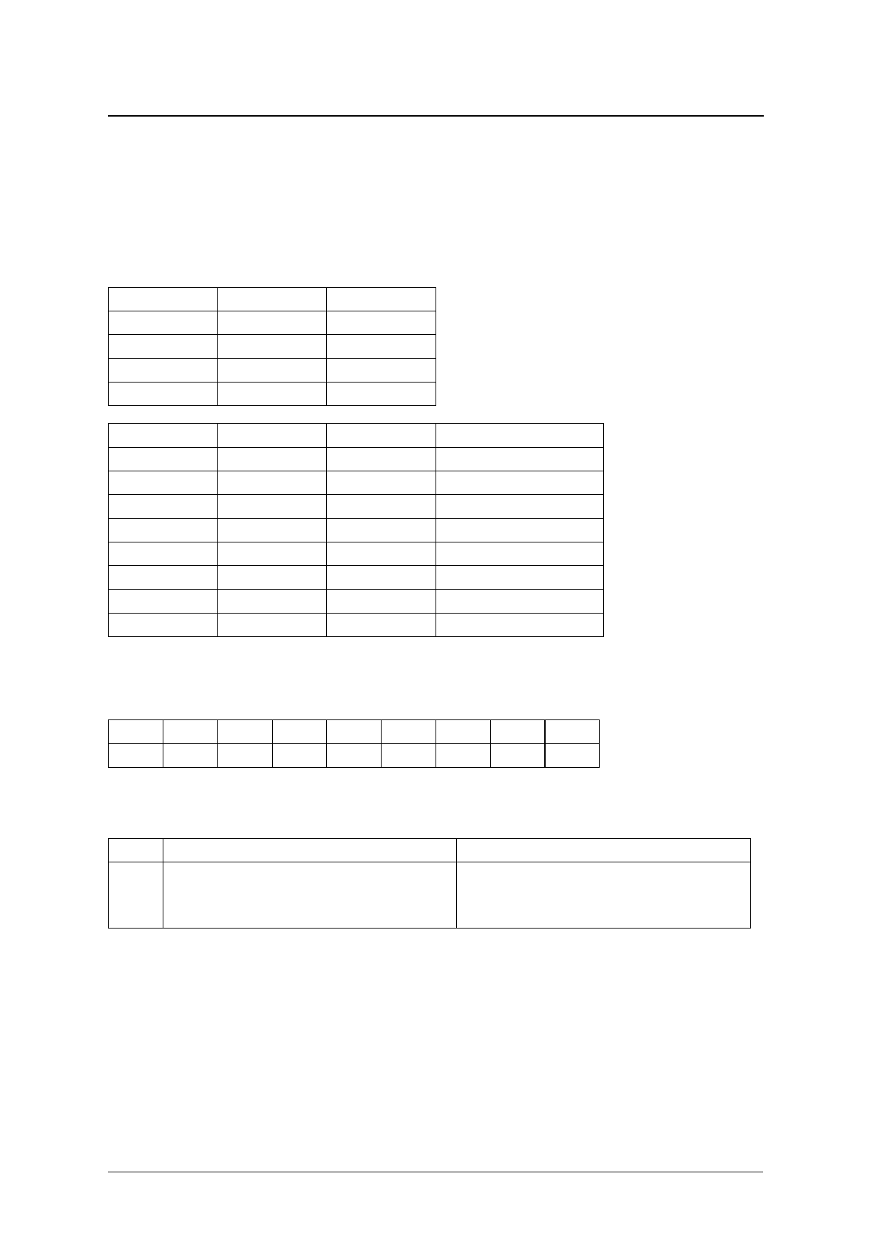
Frequency Setting Register (Register B)
I This register contains the arbitrary frequency setting for output on INTN.
The FD4 and FD3 bits set the frequency divider source clock, and the FD2 to FD0 bits set the frequency
divider ratio of the source clock (output frequency = source clock frequency × frequency divider ratio).
The FE bit must be set to “1” to enable frequency output on INTN, with frequency given by the frequency
set register (with the AIE and TIE bits set to “0”).
I When the FE bit is set to “0”, the output is disabled and is high impedance (Hi-Z).
FD4
FD3
Source clock
0
0
32768Hz
0
1
1024Hz
1
0
32Hz
1
1
1Hz
FD2
FD1
FD0
Frequency divider ratio
0
0
0
1/1
0
0
1
1/2
0
1
0
1/3
0
1
1
1/6
1
0
0
1/5
1
0
1
1/10
1
1
0
1/15
1
1
1
1/30
Control Register 1 (Register E)
This register controls alarm interrupts and timer interrupts.
Address Bit7
Bit6
Bit5
Bit4
Bit3
Bit2
Bit1
Bit0
E
*
*
*
TI/TP
AF
TF
AIE
TIE
I TI/TP bit: Interrupt Signal Output Mode Select. Interrupt/Periodic
This selects the timer interrupt signal output mode (with the FE and AIE bits set to “0”).
TI/TP
Mode
0
<Level interrupt mode>
INTN goes LOW immediately when a timer interrupt occurs.
INTN remains LOW until the TF bit is set to “0” (with TIE = “1”).
1
<Periodic interrupt mode (interval interrupt)>
INTN goes LOW immediately when a timer interrupt occurs (with
TIE = “1”), the TF bit is set to “1”, and then INTN becomes high
impedance until “0” data is written to the TF bit.
I AF, TF bits: Alarm Flag, Timer Flag
The AF bit is set to “1” when an alarm occurs, and the TF bit is set to “1” when the timer is zero.
The data bits are maintained until “0” data is written to both bits.
Note that “1” data cannot be written to both bits.
I AIE, TIE bits: Alarm, Timer Interrupt Enable
These bits determine the output on INTN when alarm or timer interrupt events occur.
AIE is the alarm interrupt enable flag, and TIE is the timer interrupt enable flag.
The alarm or timer interrupt is enabled when the corresponding enable bit is set to “1” (both interrupts are
output if both bits are set to “1”, so setting both bits to “1” should be avoided).
NIPPON PRECISION CIRCUITS INC.—9
Share Link: 