NG80960JD-66 查看數據表(PDF) - Unspecified
零件编号
产品描述 (功能)
生产厂家
NG80960JD-66 Datasheet PDF : 59 Pages
| |||
80960JD
3.0 PACKAGE INFORMATION
The 80960JD is offered with three speeds and two
package types. The 132-pin Pin Grid Array (PGA)
device is specified for operation at VCC = 3.3 V ± 5%
over a case temperature range of 0° to 100°C:
• A80960JD-66 (66 MHz core, 33 MHz bus)
• A80960JD-50 (50 MHz core, 25 MHz bus)
• A80960JD-40 (40 MHz core, 20 MHz bus)
The 132-pin Plastic Quad Flatpack (PQFP) devices
will be specified for operation at VCC = 3.3 V ± 5%
over a case temperature range of 0° to 100°C:
• NG80960JD-66 (66 MHz core, 33 MHz bus)
• NG80960JD-50 (50 MHz core, 25 MHz bus)
• NG80960JD-40 (40 MHz core, 20 MHz bus)
For complete package specifications and infor-
mation, refer to Intel’s Packaging Handbook
(240800).
3.1 Pin Descriptions
This section describes the pins for the 80960JD in
the 132-pin ceramic Pin Grid Array (PGA) package
and 132-lead Plastic Quad Flatpack Package
(PQFP).
Section 3.1.1, Functional Pin Definitions
describes pin function; Section 3.1.2, 80960Jx 132-
Lead PGA Pinout and Section 3.1.3, 80960Jx
PQFP Pinout define the signal and pin locations for
the supported package types.
3.1.1 Functional Pin Definitions
Table 2 presents the legend for interpreting the pin
descriptions which follow. Pins associated with the
bus interface are described in Table 3. Pins
associated with basic control and test functions are
described in Table 4. Pins associated with the
Interrupt Unit are described in Table 5.
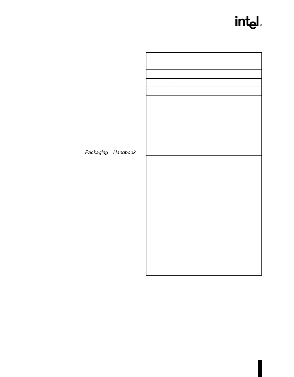
Table 2. Pin Description Nomenclature
Symbol
I
O
I/O
–
S
A (...)
R (...)
H (...)
P (...)
Description
Input pin only.
Output pin only.
Pin can be either an input or output.
Pin must be connected as described.
Synchronous. Inputs must meet setup
and hold times relative to CLKIN for
proper operation.
S(E) Edge sensitive input
S(L) Level sensitive input
Asynchronous. Inputs may be
asynchronous relative to CLKIN.
A(E) Edge sensitive input
A(L) Level sensitive input
While the processor’s RESET pin is
asserted, the pin:
R(1) is driven to VCC
R(0) is driven to VSS
R(Q) is a valid output
R(X) is driven to unknown state
R(H) is pulled up to VCC
While the processor is in the hold state,
the pin:
H(1) is driven to VCC
H(0) is driven to VSS
H(Q) Maintains previous state or
continues to be a valid output
H(Z) Floats
While the processor is halted, the pin:
P(1) is driven to VCC
P(0) is driven to VSS
P(Q) Maintains previous state or
continues to be a valid output
6
PRODUCT PREVIEW
Share Link: 