NG80960JD-66 查看數據表(PDF) - Unspecified
零件编号
产品描述 (功能)
生产厂家
NG80960JD-66 Datasheet PDF : 59 Pages
| |||
80960JD
NAME
HOLDA
BSTAT
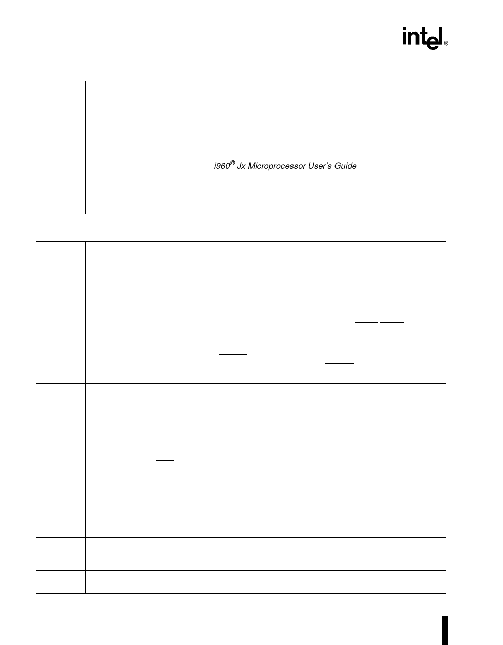
Table 3. Pin Description — External Bus Signals (Sheet 4 of 4)
TYPE
O
R(Q)
H(1)
P(Q)
O
R(0)
H(Q)
P(0)
DESCRIPTION
HOLD ACKNOWLEDGE indicates to an external bus master that the processor has
relinquished control of the bus. The processor can grant HOLD requests and enter
the Th state during reset and while halted as well as during regular operation.
0 = hold not acknowledged
1 = hold acknowledged
BUS STATUS indicates that the processor may soon stall unless it has sufficient
access to the bus; see i960® Jx Microprocessor User’s Guide (272483). Arbitration
logic can examine this signal to determine when an external bus master should
acquire/relinquish the bus.
0 = no potential stall
1 = potential stall
Table 4. Pin Description — Processor Control Signals, Test Signals and Power (Sheet 1 of 2)
NAME
CLKIN
RESET
STEST
FAIL
TCK
TDI
TYPE
I
I
A(L)
I
S(L)
O
R(0)
H(Q)
P(1)
I
I
S(L)
DESCRIPTION
CLOCK INPUT provides the processor’s fundamental time base; both the processor
core and the external bus run at the CLKIN rate. All input and output timings are
specified relative to a rising CLKIN edge.
RESET initializes the processor and clears its internal logic. During reset, the
processor places the address/data bus and control output pins in their idle (inactive)
states.
During reset, the input pins are ignored with the exception of LOCK/ONCE, STEST
and HOLD.
The RESET pin has an internal synchronizer. To ensure predictable processor initial-
ization during power up, RESET must be asserted a minimum of 10,000 CLKIN
cycles with VCC and CLKIN stable. On a warm reset, RESET should be asserted for
a minimum of 15 cycles.
SELF TEST enables or disables the processor’s internal self-test feature at initial-
ization. STEST is examined at the end of reset. When STEST is asserted, the
processor performs its internal self-test and the external bus confidence test. When
STEST is deasserted, the processor performs only the external bus confidence test.
0 = self test disabled
1 = self test enabled
FAIL indicates a failure of the processor’s built-in self-test performed during initial-
ization. FAIL is asserted immediately upon reset and toggles during self-test to
indicate the status of individual tests:
• When self-test passes, the processor deasserts FAIL and begins operation from
user code.
• When self-test fails, the processor asserts FAIL and then stops executing.
0 = self test failed
1 = self test passed
TEST CLOCK is a CPU input which provides the clocking function for IEEE 1149.1
Boundary Scan Testing (JTAG). State information and data are clocked into the
processor on the rising edge; data is clocked out of the processor on the falling edge.
TEST DATA INPUT is the serial input pin for JTAG. TDI is sampled on the rising
edge of TCK, during the SHIFT-IR and SHIFT-DR states of the Test Access Port.
10
PRODUCT PREVIEW
Share Link: 