MC12430FA 查看數據表(PDF) - Motorola => Freescale
零件编号
产品描述 (功能)
生产厂家
MC12430FA Datasheet PDF : 12 Pages
| |||
MC12430
should be adequate to eliminate power supply noise related
problems in most designs.
Jitter Performance of the MC12430
The MC12430 exhibits long term and cycle–to–cycle jitter
which rivals that of SAW based oscillators. This jitter
performance comes with the added flexibility one gets with a
synthesizer over a fixed frequency oscillator.
25
20
N=2
N=4
15
N=8
10
5
0
400
500
600
700
800
VCO Frequency (MHz)
Figure 5. RMS PLL Jitter versus VCO Frequency
Figure 5 illustrates the RMS jitter performance of the
MC12430 across its specified VCO frequency range. Note
that the jitter is a function of both the output frequency as well
as the VCO frequency, however the VCO frequency shows a
much stronger dependence. The data presented has not
been compensated for trigger jitter, this fact provides a
measure of guardband to the reported data. In addition the
data represents long term period jitter, the cycle–to–cycle
jitter could not be measured to the level of accuracy required
with available test equipment but certainly will be smaller
than the long term period jitter.
The most commonly specified jitter parameter is
cycle–to–cycle jitter. Unfortunately with today’s high
performance measurement equipment there is no way to
measure this parameter for jitter performance in the class
demonstrated by the MC12430. As a result different methods
are used which approximate cycle–to–cycle jitter. The typical
method of measuring the jitter is to accumulate a large
number of cycles, create a histogram of the edge placements
and record peak–to–peak as well as standard deviations of
the jitter. Care must be taken that the measured edge is the
edge immediately following the trigger edge. The
oscilloscope cannot collect adjacent pulses, rather it collects
pulses from a very large sample of pulses. It is safe to
assume that collecting pulse information in this mode will
produce period jitter values somewhat larger than if
consecutive cycles (cycle–to–cycle jitter) were measured. All
of the jitter data reported on the MC12430 was collected in
this manner.
25
20
15
6.25ps Reference
10
5
0
25 50 75 100 125 150 175 200 225 250 275 300 325 350 375 400
Output Frequency (MHz)
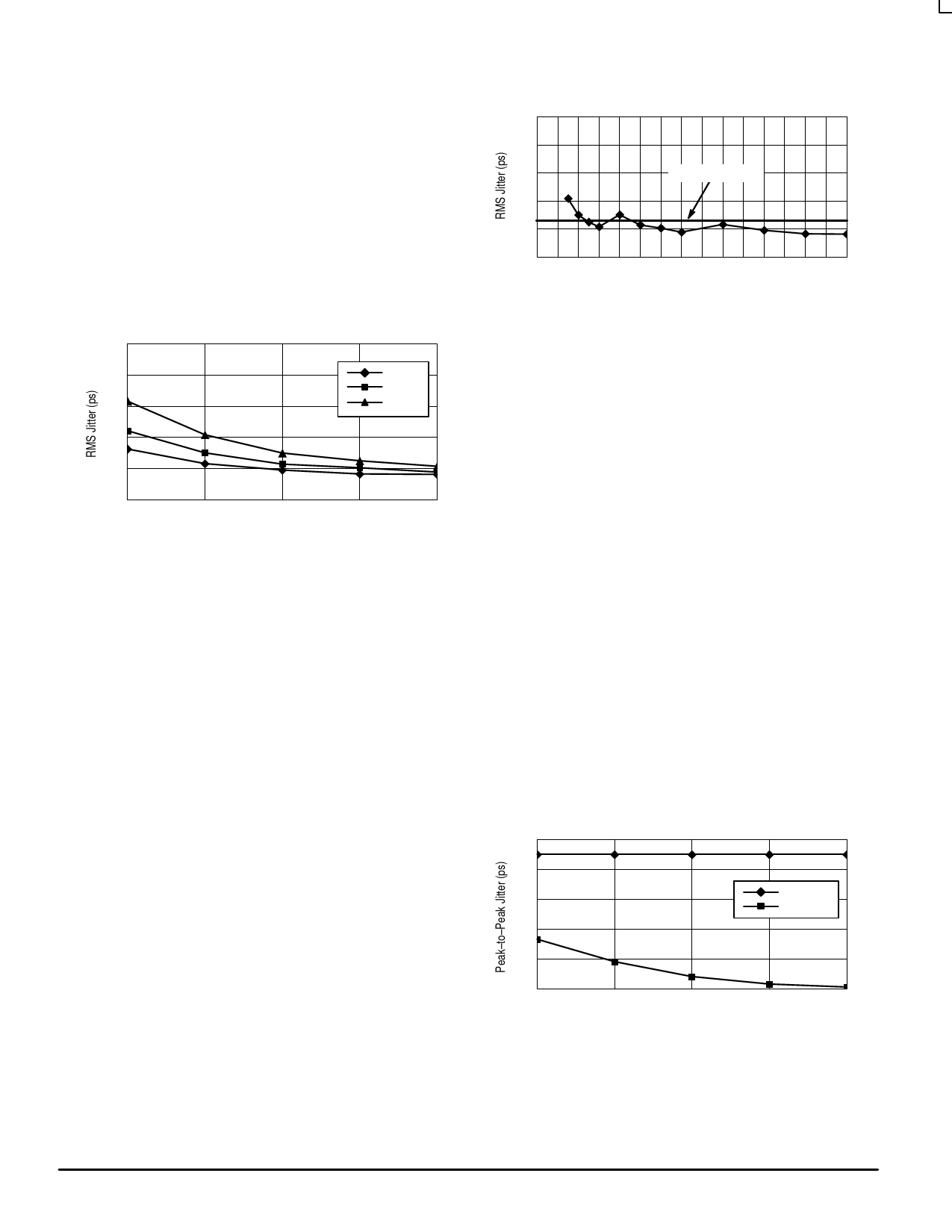
Figure 6. RMS Jitter versus Output Frequency
Figure 6 shows the jitter as a function of the output
frequency. For the 12430 this information is probably of more
importance. The flat line represents an RMS jitter value that
corresponds to an 8 sigma ±25ps peak–to–peak long term
period jitter. The graph shows that for output frequencies
from 87.5 to 400MHz the jitter falls within the ±25ps
peak–to–peak specification. The general trend is that as the
output frequency is decreased the output edge jitter will
increase.
The jitter data from Figure 5 and Figure 6 do not include
the performance of the 12430 when the output is in the divide
by 1 mode. In divide by one mode the output signal is a
digitally doubled version of the VCO output. The period of the
outputs of the digital doubler is dependent on the duty cycle
of the VCO output. Since the VCO output duty cycle cannot
be guaranteed to be always 50% the resulting 12430 output
in divide by one mode will be bimodal at times. Since a
bimodal distribution cannot be acurately represented with an
rms value, peak–to–peak values of jitter for the divide by one
mode are presented.
NO TAG shows the peak–to–peak jitter of the 12430
output in divide by one mode as a function of output
frequency. Notice that as with the other modes the jitter
improves with increasing frequency. The ±65ps shown in the
data sheet table represents a conservative value of jitter,
especially for the higher vco, and thus output frequencies.
140
120
100
Spec Limit
N=1
80
60
40
400
500
600
700
800
Output Frequency (MHz)
Figure 7. Peak–to–Peak Jitter versus
Output Frequency
The jitter data presented should provide users with
enough information to determine the effect on their overall
MOTOROLA
8
TIMING SOLUTIONS
BR1333 — Rev 6
Share Link: 