MAX17435 查看數據表(PDF) - Maxim Integrated
零件编号
产品描述 (功能)
生产厂家
MAX17435 Datasheet PDF : 27 Pages
| |||
High-Frequency,
Low-Cost SMBus Chargers
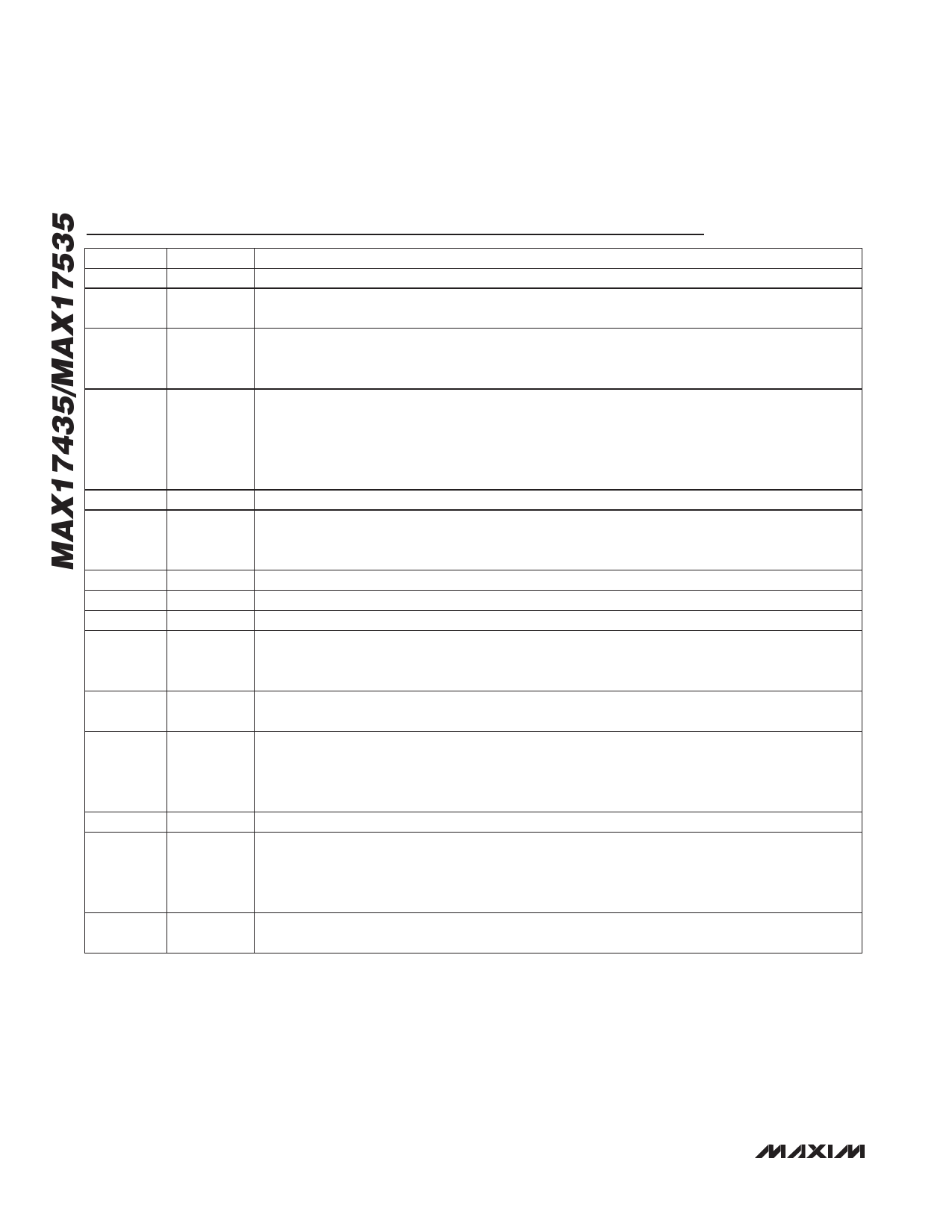
Pin Description
PIN
NAME
FUNCTION
1
SCL
SMBus Clock Input. Connect to an external pullup resistor according to SMBus specifications.
2
SDA
SMBus Data I/O. Open-drain output. Connect to an external pullup resistor according to SMBus
specifications.
Charger Supply Input. Connect to adapter supply. For minimum input bias current connect to the
3
DCIN
center of the input/soft-start FETs. Bypass with a 1FF ceramic capacitor to PGND placed close to
the pin. Add a 10ω resistor to reduce input surge at adapter insertion.
Linear Regulator Output. This is a 30mA LDO that powers the DLO driver, the BST circuit, and the
internal SMBus circuitry. Bypass with a 1FF ceramic capacitor to PGND placed close to the pin.
4
LDO
LDO is active when the Adapter Present = 1, independent of the state of EN. LDO is also active
when DCIN is supply by the battery while Adapter Present = 0 and EN is high. The SMBus registers
are reset by the rising LDO UVLO.
5
DLO
Low-Side Power-MOSFET Driver Output. Connect to low-side n-channel MOSFET gate.
Adaptive System Current-Limit Comparator Output. This open-drain output is high impedance when
6
ADAPTLIM the voltage at the IINP pin is lower than the ITHR threshold. For a typical application, use a 10kI
pullup resistor to LDO (pin 4).
7
BST
High-Side Driver Supply. Connect a 0.1FF capacitor from BST to LX.
8
LX
High-Side Driver Source Connection
9
DHI
High-Side Power MOSFET Driver Output. Connect to high-side n-channel MOSFET gate.
AC Detect Output. This open-drain output is high impedance when ACIN is lower than 1.485V.
10
ACOK
The ACOK output remains high when the MAX17435/MAX17535 are powered down. For a typical
application, use a 10kI pullup resistor to LDO (pin 4).
11
CSIN
Output Current-Sense Negative Input. Connect this pin to the negative terminal of the sense resistor.
See the Setting Charge Current section for resistor value and scaling.
Output Current-Sense Positive Input. Connect a current-sense resistor from CSIP to CSIN; the
12
CSIP
voltage across these two pins is interpreted by the MAX17435/MAX17535 as proportional to the
charge current delivered to the battery with approximately 110mV full-scale voltage. See the Setting
Charge Current section for resistor value and scaling.
13
BATT
Battery Voltage Feedback Input. Connect as close as possible to the battery terminal.
Power-Source n-Channel MOSFET Switch Driver Output. When the adapter is not present or an
14
PDSL
overvoltage event is detected at the input, the PDSL output is pulled to GND with a 2.5kI (typ)
resistor. Otherwise, it is typically 8V above the adapter voltage when the part is not using the
battery. This is powered by an internal charge pump.
15
CSSN
Input Current-Sense Negative Input. See the description of the CSSP pin for resistor value and
scaling.
12 �������������������������������������������������������������������������������������
Share Link: 