MAX17435 查看數據表(PDF) - Maxim Integrated
零件编号
产品描述 (功能)
生产厂家
MAX17435 Datasheet PDF : 27 Pages
| |||
High-Frequency,
Low-Cost SMBus Chargers
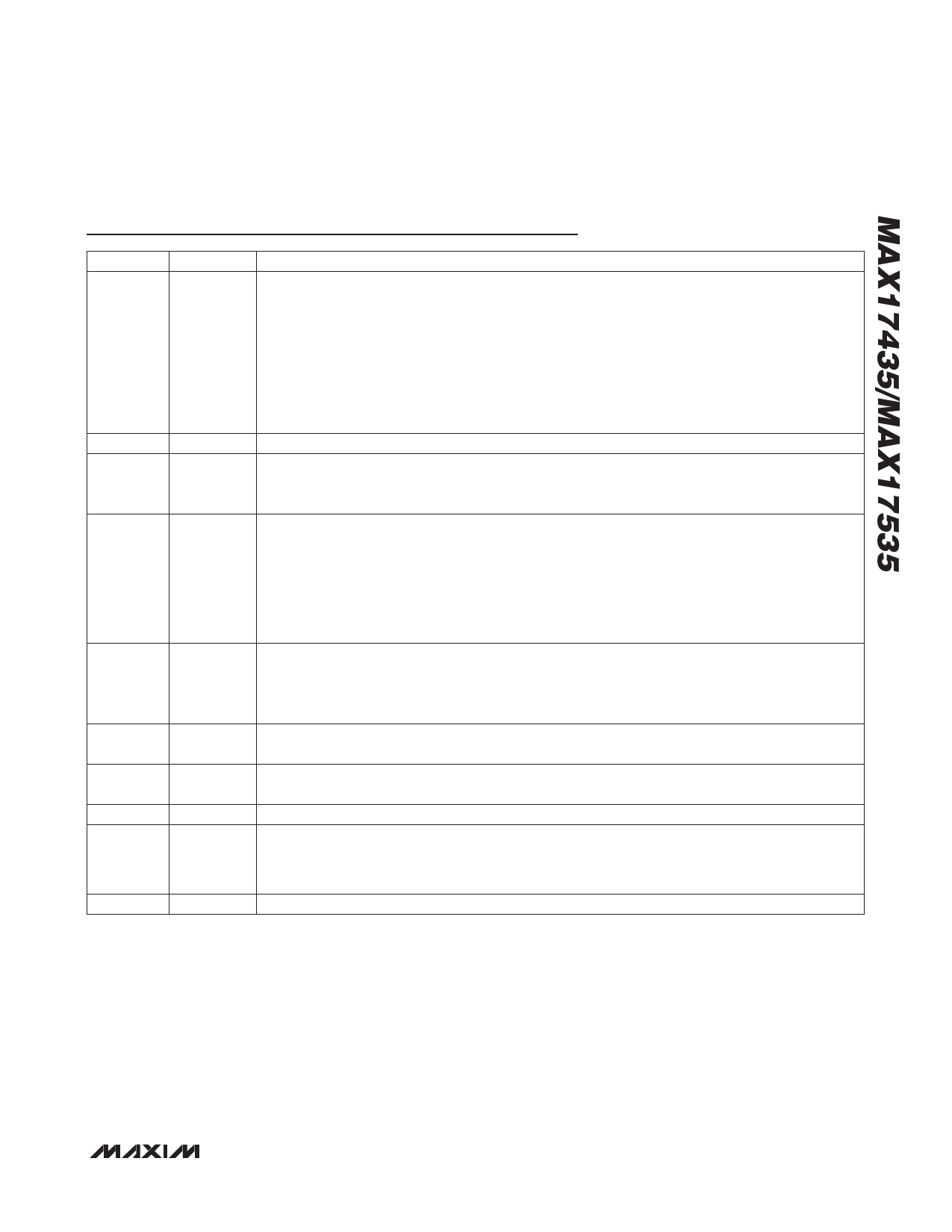
Pin Description (continued)
PIN
NAME
FUNCTION
Current Sense for Positive Input. Connect a current-sense resistor from CSSP to CSSN. The voltage
across CSSP to CSSN determines the current at which the charger reduces charging current to
keep from drawing more current from the adapter than is allowed. As the system current flowing in
the resistor from CSSN to CSSP increases, the charger reduces charge current to keep the system
16
CSSP
current at the limit value. When the system current reaches 130% of InputCurrent() setting for more
than 16ms, the PDSL pin turns off the adapter selector FET to prevent excess current from being
drawn from the adapter. The adaptor selector FET is re-enabled after 0.6s. If the fault continues, the
cycle is repeated three times after which the MAX17435/MAX17535 is latched off. To reset the latch,
remove and reinsert the adapter.
17
CC
Voltage Regulation Loop-Compensation Point. Connect a 10nF capacitor from CC to GND.
Input Current-Monitor Output. The voltage at the IINP pin is 20 times the voltage from CSSP to
18
IINP
CSSN. This voltage is present when charging is enabled to monitor the system current, and when
the battery is discharging to monitor the battery discharge current.
AC Adapter-Detect Input. ACIN is the input to a comparator with a 1.485V (typ) reference voltage.
The output of the comparator is ACOK. ACOK goes low when the threshold voltage is exceeded,
indicating that the AC adapter is present, and it enables the charger. When the ACIN input is above
19
ACIN
2.0V, the MAX17435/MAX17535 interpret that as an adapter overvoltage event. The charger is then
disabled and the adapter MOSFETs are turned off. If the part is charging and the ACIN voltage
drops below the programmed threshold, the charger is disabled, and a ChargeCurrent() and
ChargeVoltage() command have to be written over the SMBus to re-enable the charger.
Adaptive System Current-Limit Comparator Threshold. This pin connects to the inverting input of a
20
ITHR
comparator. The noninverting input of the comparator is the IINP input, while the output is driving
the ADAPTLIM open drain. When the input to ITHR is greater than IINP, the ADAPTLIM output is
high.
21
VAA
4.096V Internal Reference Voltage; No External Load Allowed. Bypass to analog ground using a 1FF
or greater ceramic capacitor. VAA is active only after LDO and the internal reference are active.
22
VCC
Circuitry Supply-Voltage Input. Connect to LDO through 10I and bypass with a 0.1FF capacitor to
GND as close as possible to the package pin.
23
GND
Analog Ground
Enable/Disable Charger Operation. This disables the charger and associated circuitry when EN
24
EN
goes low and is in addition to the ACOK charger enable. If the adapter is absent and EN is pulled
up to a voltage higher than 2.4V, LDO, VAA, the input charge current, and the battery discharge
current monitor on IINP are enabled.
—
EP
Exposed Pad. Connect backside EP to power ground.
______________________________________________________________________________________ 13
Share Link: 