AT88SC1003 查看數據表(PDF) - Atmel Corporation
零件编号
产品描述 (功能)
生产厂家
AT88SC1003 Datasheet PDF : 30 Pages
| |||
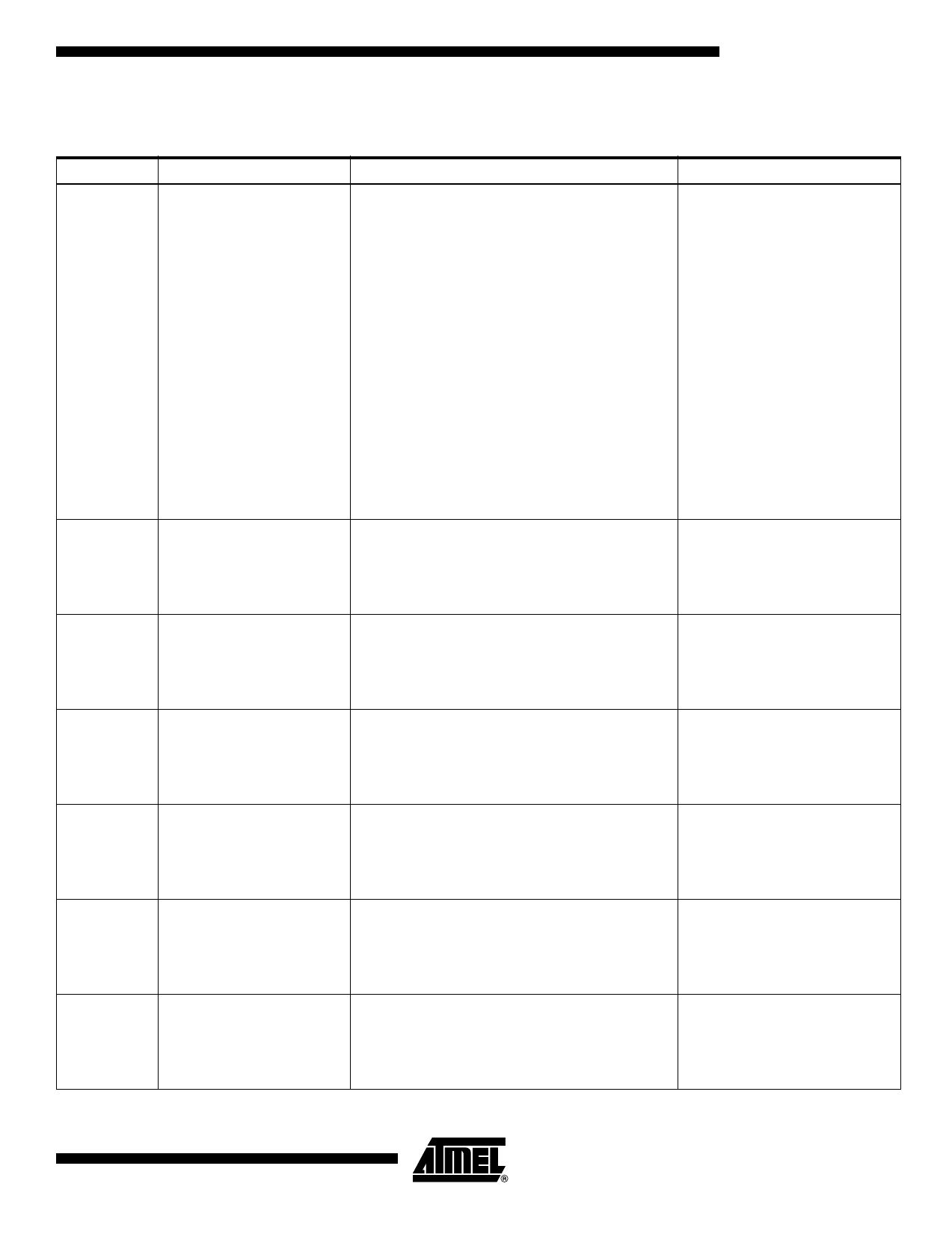
AT88SC1003
Internal Flags
Table 4. Definition of AT88SC1003 Internal Flags
Flag
Definition
Operation
SV
Security Validation Flag
The SV flag is set by correctly matching the 16-bit
security code bit by bit from address 80 through
95, as pin CLK increments the address counter.
The security code matching operation must be
followed immediately by a validation operation
within the Security Code Attempts Counter
(SCAC). This validation operation requires the
user to find a bit in the SCAC, addresses 96–99,
that is a logic “1”. A write is performed followed by
an erase. The AT88SC1003 will validate that the
comparison was correct by outputting a logic “1”,
and SV will be set. After the erase, all 16 bits in
the SCAC will also be erased. The flag remains
set until power to the card is turned off. If the
comparison was in error or part of the validation
was not performed correctly, the AT88SC1003 will
output a logic “0” showing that SV has not been
set. After four consecutive incorrect security code
presentations, the card is permanently locked.
P1
Application Zone 1 Write
If Bit 176 has been programmed to a logic “1”, this
Flag
flag is set after Bit 176 has been addressed. The
flag remains set until power to the device is turned
off, even if this bit is written to “0” by a subsequent
operation.
P2
Application Zone 2 Write
If Bit 480 has been programmed to a logic “1”, this
Flag
flag is set after Bit 480 has been addressed. The
flag remains set until power to the device is turned
off, even if this bit is written to “0” by a subsequent
operation.
P3
Application Zone 3 Write
If Bit 1024 has been programmed to a logic “1”,
Flag
this flag is set after Bit 1024 has been addressed.
The flag remains set until power to the device is
turned off, even if this bit is written to “0” by a
subsequent operation.
R1
Application Zone 1 Read
If Bit 177 has been programmed to a logic “1”, this
Flag
flag is set after Bit 177 has been addressed. The
flag remains set until power to the device is turned
off, even if this bit is written to “0” by a subsequent
operation.
R2
Application Zone 2 read flag If Bit 481 has been programmed to a logic “1”, this
flag is set after Bit 481 has been addressed. The
flag remains set until power to the device is turned
off, even if this bit is written to “0” by a subsequent
operation.
R3
Application Zone 3 Read
If Bit 1025 has been programmed to a logic “1”,
Flag
this flag is set after Bit 1025 has been addressed.
The flag remains set until power to the device is
turned off, even if this bit is written to “0” by a
subsequent operation.
Function
This flag is the master protection
for the memory zones. See
Table 6 and Table 7.
P1 and SV must both be set in
order to enable a write command
in Application Zone 1 (Security
Mode 2).
P2 and SV must both be set in
order to enable the write
command in Application Zone 2
(Security Mode 2).
P3 and SV must both be set in
order to enable a write command
in Application Zone 3 (Security
Mode 2).
R1 or SV must be set to “1” in
order to enable Application Zone
1 bits to be read.
R2 or SV must be set to “1” in
order to enable Application Zone
2 bits to be read.
R3 or SV must be set to “1” in
order to enable Application Zone
3 bits to be read.
9
2035B–SMEM–08/03
Share Link: 