LTC1700EMS 查看數據表(PDF) - Linear Technology
零件编号
产品描述 (功能)
生产厂家
LTC1700EMS Datasheet PDF : 16 Pages
| |||
LTC1700
APPLICATIONS INFORMATION
preferred at high switching frequencies, so design goals
can concentrate on copper loss and preventing saturation.
Ferrite core material saturates “hard”, which means that
inductance collapses abruptly when the peak design cur-
rent is exceeded. This results in an abrupt increase in
inductor ripple current and output voltage ripple. Do not
allow the core to saturate!
Molypermalloy (from Magnetics, Inc.) is a very good, low
loss core material for toroids, but it is more expensive than
ferrite. A reasonable compromise from the same manu-
facturer is Kool Mµ. Toroids are very space efficient,
especially when you can use several layers of wire. Be-
cause they generally lack a bobbin, mounting is more
difficult. However, new designs for surface mount are
available which do not increase the height significantly.
COUT Selection
During continuous operation, the output capacitor has a
trapezoidal current profile. The RMS current into the
capacitor is then given by:
⎛
ICOUT(RMS) ≅ ⎝⎜IOUT
VOUT
VIN
⎞
– 1⎠⎟
The RMS current is greatest at IOUT(MAX) and minimum
input working voltage. Therefore the output capacitor
should be chosen with a rating at least ICOUT(RMS). Several
capacitors can also be paralleled to meet this requirement.
Besides RMS current rating, the selection of COUT is also
driven by the required effective series resistance (ESR).
The ESR of the capacitor together with its capacitance
determines the output ripple voltage and can be expressed
as:
( ) ∆VOUT
≈ IPK
ESR
+ 2IOUT
C OUT
tON
where COUT = output capacitance, tON = on time of main
MOSFET and IPK = peak inductor current. A common
technique to lower the total ESR at the output is to parallel
the output capacitor with a 10µF ceramic capacitor.
The choice of using a smaller output capacitance in-
creases the output ripple voltage due to the frequency
dependent term but can be compensated for by using
capacitors of very low ESR to maintain low ripple voltage.
The ITH pin OPTI-LOOP compensation components can be
optimized to provide stable, high performance transient
response regardless of the output capacitors selected.
Manufacturers such as Nichicon, United Chemicon and
Sanyo should be considered for high performance through-
hole capacitors. The OS-CON semiconductor dielectric
capacitor available from Sanyo has the lowest ESR (size)
product of any aluminum electrolytic at a somewhat
higher price.
Multiple capacitors may have to be paralleled to meet the
ESR or RMS current handling requirements of the applica-
tion. Aluminum electrolytic and dry tantalum capacitors
are both available in surface mount configurations. In the
case of tantalum, it is critical that the capacitors are surge
tested for use in switching power supplies. An excellent
choice is the AVX TPS series of surface mount tantalum,
available in case heights ranging from 2mm to 4mm. Other
capacitor types include Sanyo OS-CON, Nichicon PL se-
ries and Sprague 593D and 595D series. Consult the
manufacturer for other specific recommendations.
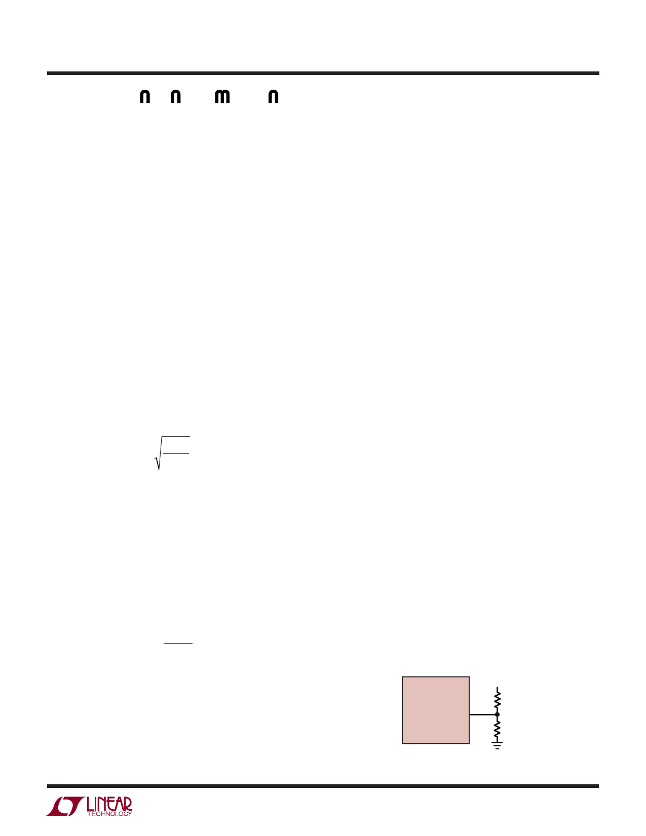
Setting Output Voltage
The LTC1700 develops a 1.205V reference voltage be-
tween the feedback (Pin 3) terminal and ground (see
Figure 6). By selecting resistor R1, a constant current is
caused to flow through R1 and R2 to set the overall output
voltage. The regulated output voltage is determined by:
VOUT = 1.205(1 + R2/R1)
For most applications, a 30k resistor is suggested for R1.
To prevent stray pickup, a 100pF capacitor is suggested
across R1 located close to LTC1700.
Efficiency Considerations
LTC1700
VFB
VOUT
R2
R1
1700 • F06
Figure 6. Setting Output Voltage
1700fa
11
Share Link: 