NX25F011A 查看數據表(PDF) - NexFlash -> Winbond Electronics
零件编号
产品描述 (功能)
生产厂家
NX25F011A
NexFlash -> Winbond Electronics

NX25F011A Datasheet PDF : 26 Pages
| |||
NX25F011A
NX25F041A
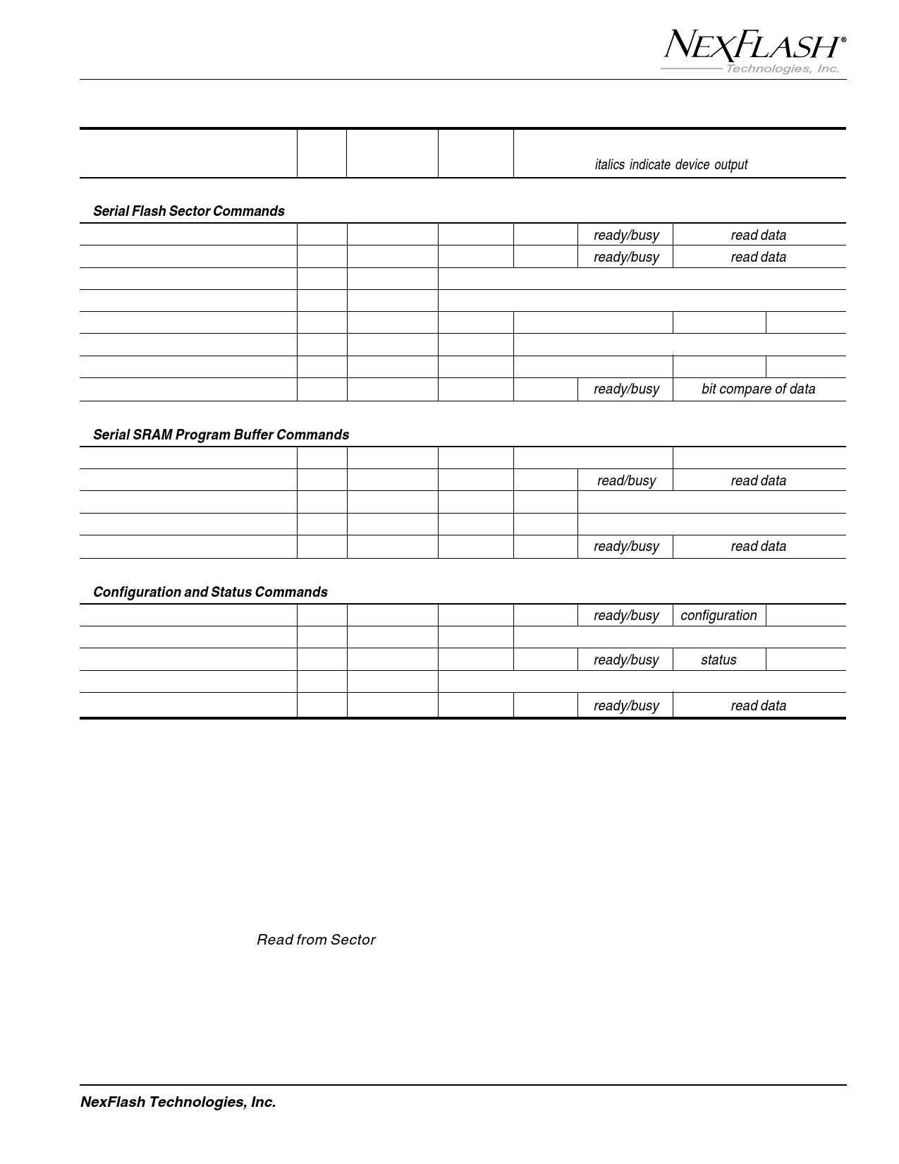
Table 3. Command Set for the NX25F011A, and NX25F041A Serial Flash Memory
n - bytes
Command Name
Byte 0 Byte 1-2 Byte 3-4
(italics indicate device output)
1
Serial Flash Sector Commands
Read from Sector
52H sector addr. byte add. 0000H ready/busy
Read from Sector Low Frequency 51H sector addr. byte add. 0000H ready/busy
read data
read data
2
Write Enable*
06H
00H
Write Disable*
04H
00H
Write to SectorF3H
sector addr. byte add.
write data
00H
3
Transfer SRAM to Sector
F3H sector addr. 0000H
Transfer Sector to SRAM
54H sector addr. byte add. clock 00H per byte
00H
Compare Sector with SRAM
86H sector addr. byte add. 0000H ready/busy
bit compare of data
4
Serial SRAM Program Buffer Commands
Write to SRAM**
Read from SRAM*
82H
0000H
byte add.
write data
81H
0000H
byte add. 0000H read/busy
00H
read data
5
Transfer SRAM to Prog. Buffer 92H
0000H
0000H 0000H
Transfer Prog. Buffer to SRAM 55H
0000H
0000H 0000H
Read from Program Buffer
91H
0000H
byte add. 0000H ready/busy
read data
6
Configuration and Status Commands
Read Configuration Register*
8BH
0000H
0000H 0000H ready/busy configuration
7
Write Configuration Register
8AH configuration 0000H
Read Status Register*
83H
0000H
0000H 0000H ready/busy
status
Clear Compare Status*
89H
0000H
8
Read Device Information Sector 15H
0000H
byte add. 0000H ready/busy
read data
Notes:
1. * Command may be used when device is busy
2. ** Command may not be used when device is busy and TR bit=0
9
SERIAL FLASH SECTOR COMMANDS
Read From Sector
Reading from a sector is accomplished by first bringing
CS low then shifting in the Read from Sector command
(52H) followed by its 16-bit “sector-address” field.
Although the sector-address field is 16-bits, only bits
S[8:0] for the NX25F011A (0-1FFH) and S[10:0] for the
NX25F041A (0-7FFH) are used. The uppermost sector
address bits are not used but must be clocked using 0
10
11 for data. Next a 16-bit “byte-address” field is clocked
into the device to designate the starting location within
the 264-byte sector. Only B[8:0] of the byte-address
12 field are used; the uppermost bits are not used but must
be clocked in (use 0 for data). Only byte-addresses of
0 to 107H (264 bytes) are valid.
NexFlash Technologies, Inc.
11
PRELIMINARY NXSF014B-0699
06/11/99
Share Link: